Narrow shoe journal microfinishing apparatus and method

a microfinishing and shoe journal technology, applied in metal-working apparatus, superfinishing machines, belt grinding machines, etc., can solve the problems of limiting the load carrying capacity and performance of bearings, affecting the service life of the journal, and requiring long service life for owners and operators of such equipment, so as to achieve flexible journal diameter and sufficient compliance of the tooling backing.

Pending Publication Date: 2021-04-08
IMPCO MICROFINISHING
View PDF3 Cites 0 Cited by
  • Summary
  • Abstract
  • Description
  • Claims
  • Application Information

AI Technical Summary

Benefits of technology

[0010]In accordance with the present invention, an apparatus and methods specifically suited for crankshaft microfinishing are described providing numerous benefits over current techniques and devices. Two principal features are described, one feature enables providing standardized machines and tooling for a variety of crankshaft configurations. Another area of enhancements according to the invention is related to producing desired journal bearing surface shape. Both features of the invention are realized utilizing microfinishing tooling with shoes having a width significantly less than the axial length of the journal surface to be machined. The narrow tooling width or “thin shoe” design permits journals over a range of axial length to be machined using common tooling. In one implementation of the present invention, a shoe width is less than 50% (and preferably less than 40%) of the journal bearing axial length, while greater than about 20% of the length. Additional benefits are provided through precise control over one or more of various machining parameters during microfinishing including, applied shoe clamping force, tool oscillation, and tool stroking which can be implemented to generate the desired journal profile shapes. These parameters take advantage of the tailored machining capabilities using the “thin shoe” configuration since they permit regions of the journal surface to be machined with a different effect than other regions. Furthermore, with sufficient compliance in the tooling backing, some flexibility of journal diameter can also be accommodated with individual tools.

Problems solved by technology

Improperly finished bearing surfaces may lead to premature bearing failure and can limit the load carrying capacity and performance of the bearing.
Moreover, owners and operators of such equipment require long service lives with low warranty claims and maintenance requirements.
Microfinishing operations ordinarily take place after a grinding process which produces the desired journal geometry, but such processes in general do not provide desired surface finish parameters.
Crankshaft microfinishing operations available today are limited in their capabilities of correcting geometric errors in incoming workpieces and in forcing the workpiece to a desired profile configuration.
Microfinishing tooling for internal combustion crankshafts must operate within the confines of the axial length of the journal bearing surface being machined since crankshaft structures such as the throws, webs, flanges, and gears present between the bearing surfaces interfere at the axial ends of the journals.
Micromachining workpieces with different dimensional specifications typically requires tooling changeover with the attendant operational downtime and manpower commitments.

Method used


Image

  • Narrow shoe journal microfinishing apparatus and method
  • Narrow shoe journal microfinishing apparatus and method
  • Narrow shoe journal microfinishing apparatus and method

Examples


Embodiment Construction

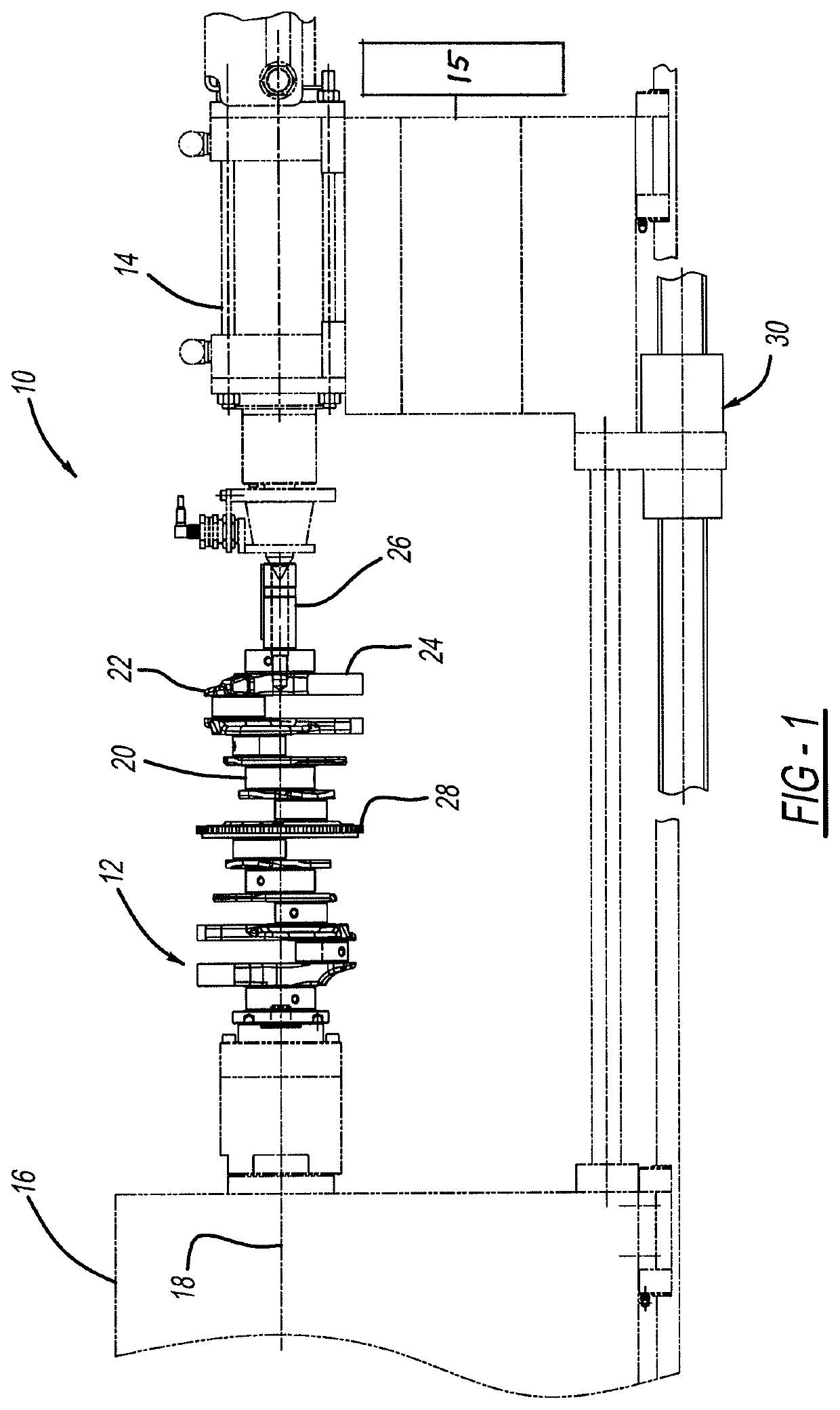
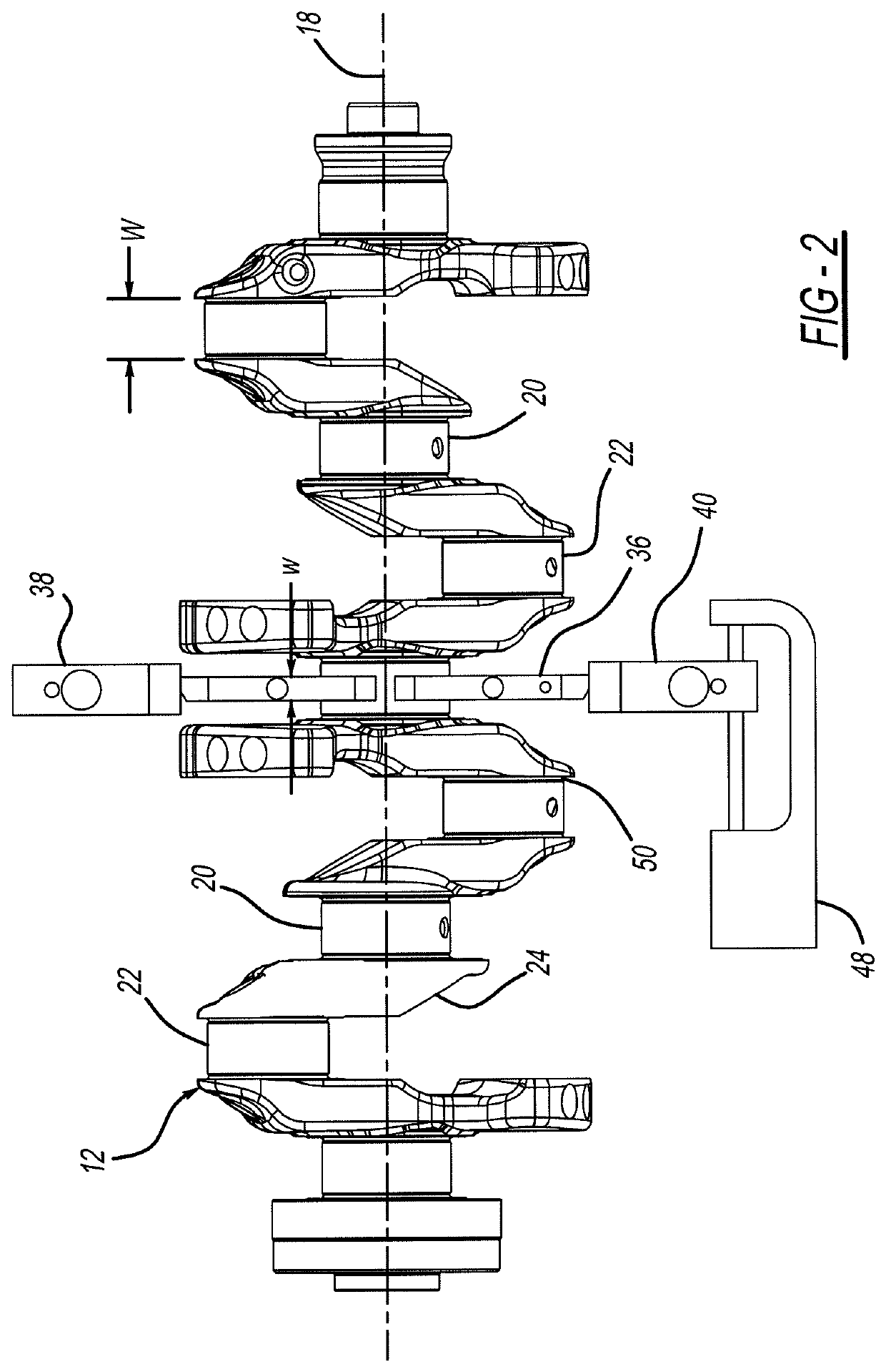
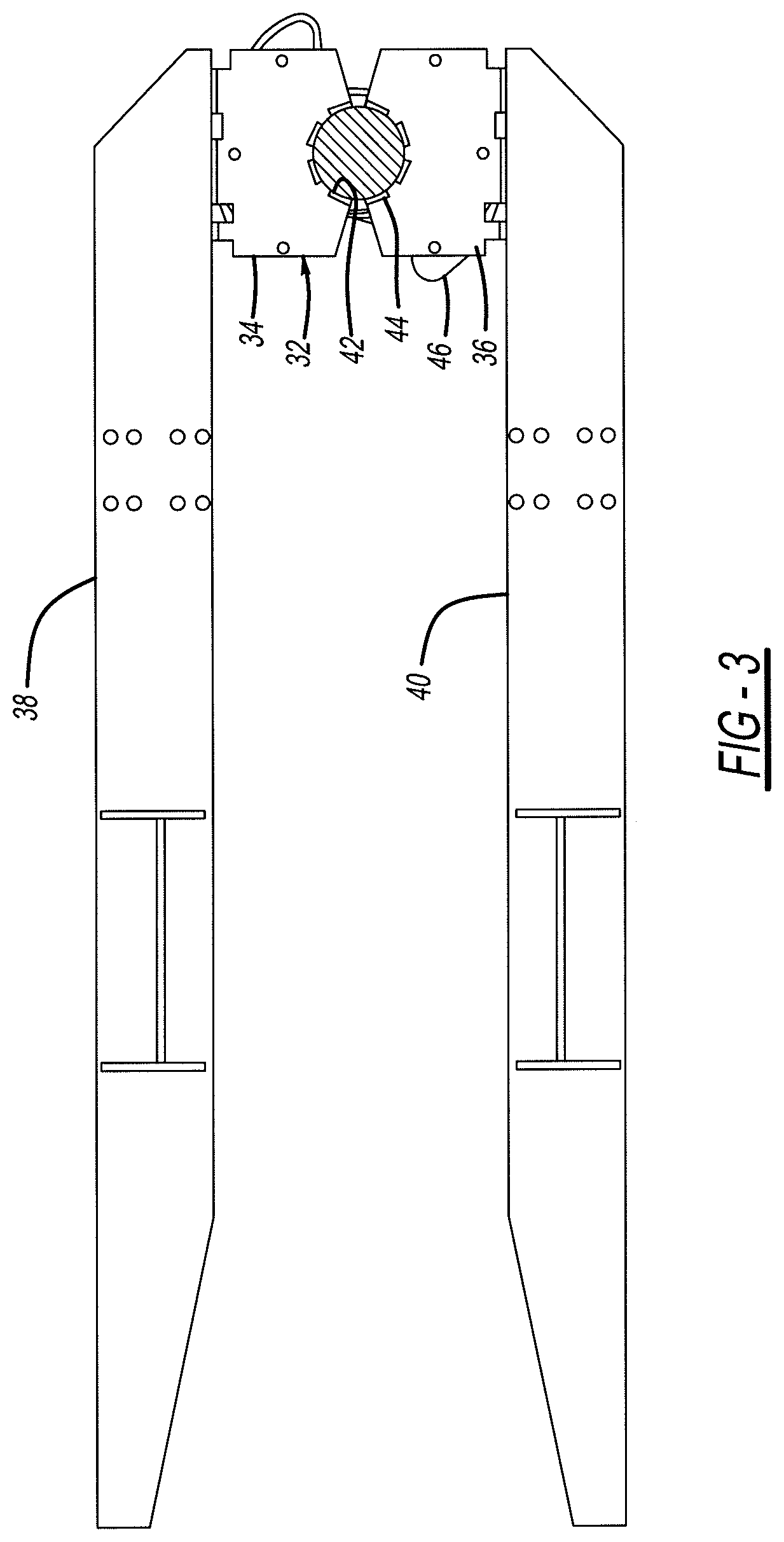
[0018]FIGS. 1, 2 and 3 illustrate a microfinishing machine 10 in accordance with the present invention and which is capable of being operated to practice the methods in accordance with the present invention. As shown by the figures, a representative workpiece shown as internal combustion engine crankshaft 12 is supported at opposing ends by machine headstock 14 and tailstock 15 which together cause crankshaft 12 to be rotated about its longitudinal center axis 18. Crankshaft 12 forms a number of cylindrical journal bearing surfaces to be microfinished, including main bearing journals 20 (four shown in FIG. 1) which are concentric with axis 18, and rod bearing journals 22 (six shown in FIG. 1) which move in rotational and orbital paths upon rotation of crankshaft 12. Since crankshaft 12 is rotated about its longitudinal axis 18 which is coaxial with main journals 20, their centers remain theoretically stationary during rotation of the crankshaft. Crankshaft 12 includes a number of st...


PUM


Abstract

A microfinishing machine and method especially adapted for processing of internal combustion engine crankshafts and other workpieces. Microfinishing is achieved by tooling having abrasive inserts or which present abrasive coated film against the journal to be machined. The tooling has a width less than one-half the length of the journal being machined. The narrow width tooling allows a range of workpiece configurations to be processed with common tooling, and through control of one or more of machining parameters including clamping pressure acting on the tooling, oscillation of the tooling, and stroking schedule of the tooling, desired journal contour profiles can be produced.

Description

CROSS REFERENCE TO RELATED APPLICATION[0001]This application claims priority to U.S. Provisional Application No. 62 / 289,382, filed on Feb. 1, 2016.FIELD OF THE INVENTION[0002]This invention relates to metal finishing and to an improved apparatus and methods for microfinishing metal cylindrical surfaces with particular applicability for journal bearing surfaces of internal combustion crankshafts.BACKGROUND[0003]Numerous types of machinery components must have finely controlled surface finishes in order to perform satisfactorily. For example, fine surface finish control provided by an abrading tool or abrasive media, also referred to as microfinishing, is particularly significant in relation to the manufacturing of journal bearing and cam surfaces such as are found in internal combustion engine crankshafts, camshafts, power transmission shafts, and other machine-finished surfaces. For journal type bearings, very accurately formed journal surfaces are needed to provide the desired hydr...

Claims


Application Information

Patent Timeline
Patent Type & Authority Applications(United States)
IPC IPC(8): B24B5/42B24B35/00
CPCB24B5/421B24B19/125B24B35/00B24B5/42B24B21/22B24B21/02
Inventor HENDEL, MARKPORUBSKY, JOE
Owner IMPCO MICROFINISHING
Why Eureka
Try Eureka