Protection device of vehicle cylinder lock

A technology of protection device and pin lock, which is applied in vehicle locks, devices for preventing theft of bicycles, application of locks, etc., can solve problems such as complex shape, limited freedom of choice of opening and closing plates, difficulty in strength of opening and closing plates, etc., to achieve The effect of increasing degrees of freedom

Inactive Publication Date: 2004-02-04
HONDA LOCK MFG CO LTD
View PDF1 Cites 9 Cited by
  • Summary
  • Abstract
  • Description
  • Claims
  • Application Information

AI Technical Summary

Problems solved by technology

In addition, due to its complex shape, the rotating part forming part of the magnetic lock is generally formed by die casting, and the strength of the molded product cannot be said to be high, so it is difficult to obtain high stren

Method used


Image

  • Protection device of vehicle cylinder lock
  • Protection device of vehicle cylinder lock
  • Protection device of vehicle cylinder lock

Examples


Embodiment Construction

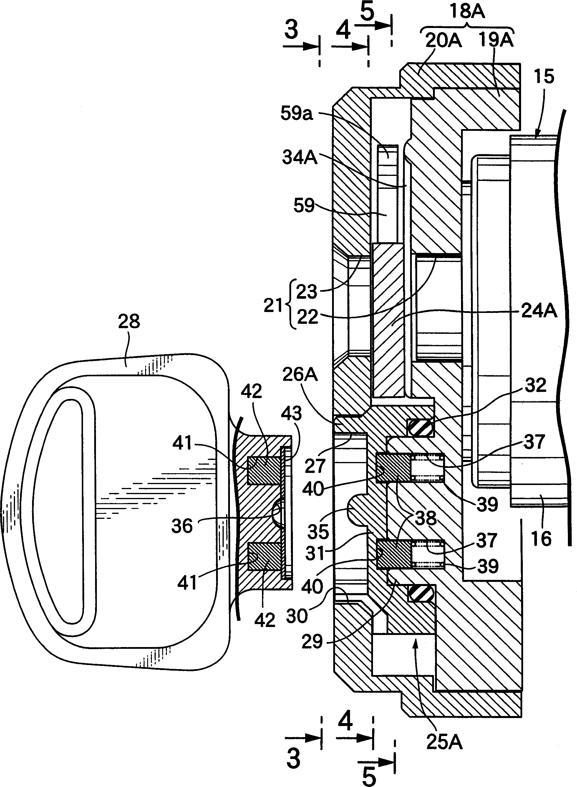
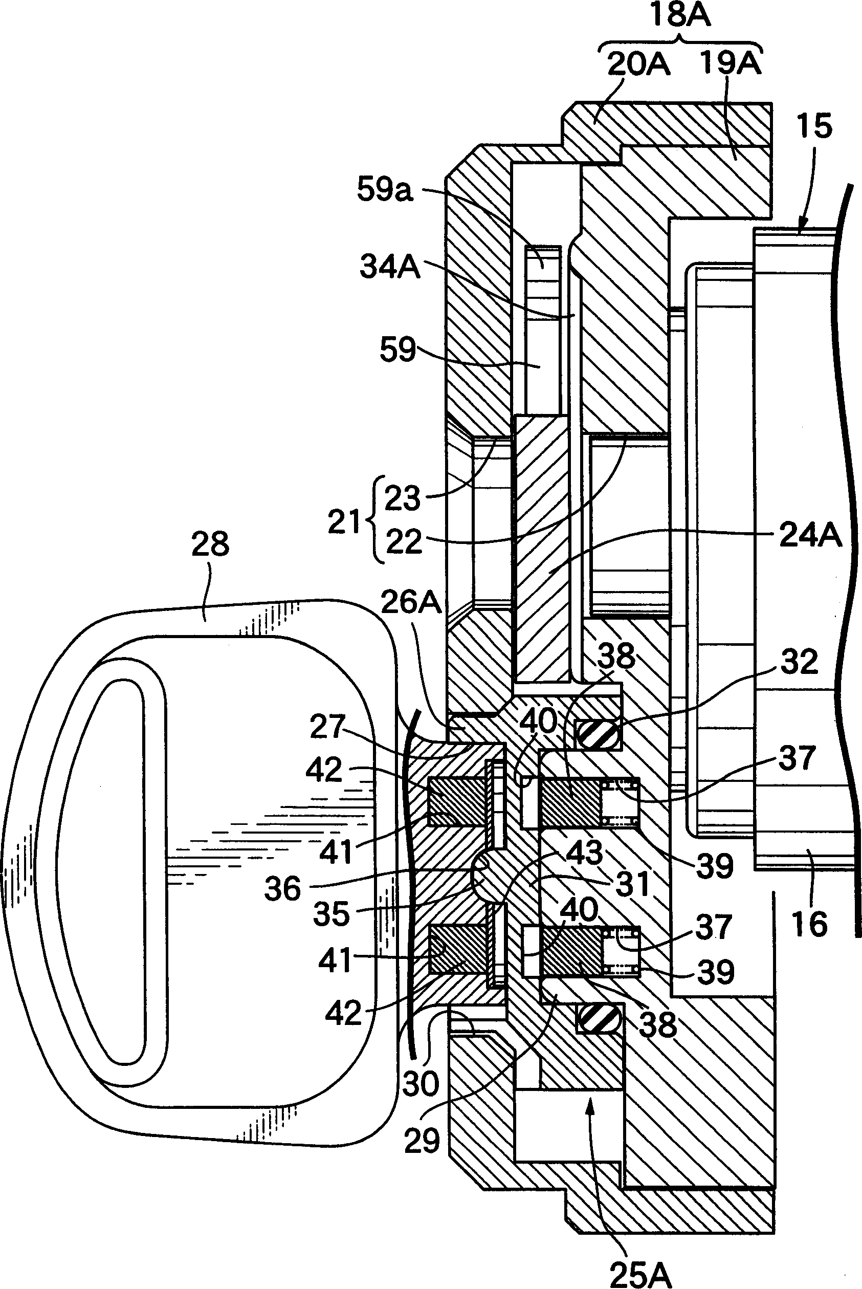
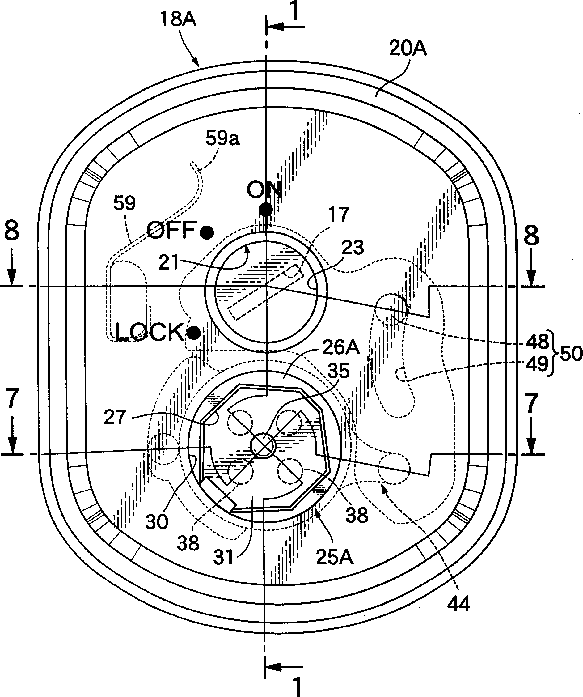
[0012] Refer below Figure 1 to Figure 8 , to describe the first embodiment of the present invention, first, in figure 1 and figure 2 In the vehicle, for example, the cylindrical body 16 of the cylinder lock 15 used for motorcycles is arranged on the head tube (not shown in the figure) of the vehicle frame, and the front end of the cylindrical body 16 is fixed on the side of the vehicle frame. Covered by housing 18A. The casing 18A is composed of a case member 19A made of a non-magnetic material attached to the front end portion of the cylindrical body 16 , and a cover member 20A made of a non-magnetic material attached to the case member 19A.

[0013] Also refer to image 3 , In the housing 18A, an insertion hole 21 is opened, and the insertion hole 21 corresponds to the key hole 17 provided in the middle part of the front end of the cylinder lock 15 . The insertion hole 21 is composed of through holes 22 and 23 respectively opened in the housing part 19A and the cover p...


PUM


Abstract

A protector of a cylinder lock for a vehicle in which a shutter plate, which is capable of operation between a closed position where an insertion hole corresponding to a keyhole of the cylinder lock is closed and an open position where the insertion hole is open, is housed in a casing, and in which a magnet lock that allows the operation of the shutter plate from the closed position to the open position during the engagement of the magnet key into the engagement concavity is disposed in the casing, wherein the magnet lock (25A) is formed separately from the shutter plate (24A) and is provided with a rotor (26A) in which the engagement concavity (27) is provided, the rotor (26A) being connected to the shutter plate (24A) via a link mechanism (44). This increases the degree of freedom in the selection of the material and manufacturing method of the shutter plate and enables the shutter plate to be formed from a high-strength material.

Description

technical field [0001] The present invention relates to a protection device for a cylinder lock for a vehicle, comprising: a casing having an insertion hole corresponding to a keyhole of the cylinder lock; It moves between the locked position of closing the above insertion hole and the open position of opening the above insertion hole, and is received inside the above housing; the magnetic lock has a fitting recess that can be inserted and pulled out to fit the magnetic key, according to The housing is provided in such a manner that when the magnetic key is fitted into the fitting recess, the opening and closing plate is allowed to move from the locked position to the opened position. Background technique [0002] In the past, the above-mentioned device has been disclosed in, for example, JP-A-2000-104426. [0003] However, in the above-mentioned conventional devices, the rotating member provided with the magnetic lock and the opening and closing plate are integrally formed...

Claims


Application Information

Patent Timeline
IPC IPC(8): E05B17/18B62H5/06E05B17/14E05B47/00E05B77/44E05B83/00
CPCE05B47/0038B60R25/2063E05B17/142B60R25/04
Inventor 桥本学
Owner HONDA LOCK MFG CO LTD
Why Eureka
Try Eureka