Timer of electric timepiece

An electric and horological technology, applied in electric mechanical clocks, spring ratchet mechanisms, clocks, etc., can solve problems such as increased cost, incorrect time display, and mechanical difficulties.

Inactive Publication Date: 2004-02-04
CITIZEN WATCH CO LTD
View PDF0 Cites 10 Cited by
  • Summary
  • Abstract
  • Description
  • Claims
  • Application Information

AI Technical Summary

Problems solved by technology

[0004] In order to save power, stop the pointer display, and only use the electric counting circuit to keep the time, and then drive the pointer to display the time in the charging state. Clocks and watches using this method have been sold, but after charging from the beginning to full charging Incorrect time will be displayed during the time, which cannot meet the requirements of users who need to always display the correct time
[0005] It has been considered to have a plurality of gear trains for driving the second hand and gear trains for driving the hour, minute, calendar, etc., and to stop only the second hand driving train when the stored energy is insufficient. However, since two motors are used, will increase in size and weight
Therefore, it becomes an expensive timepiece due to the increase in cost
Therefore, a mechanism for a small, thin and inexpensive practical clock is difficult

Method used


Image

  • Timer of electric timepiece
  • Timer of electric timepiece
  • Timer of electric timepiece

Examples


Embodiment 2

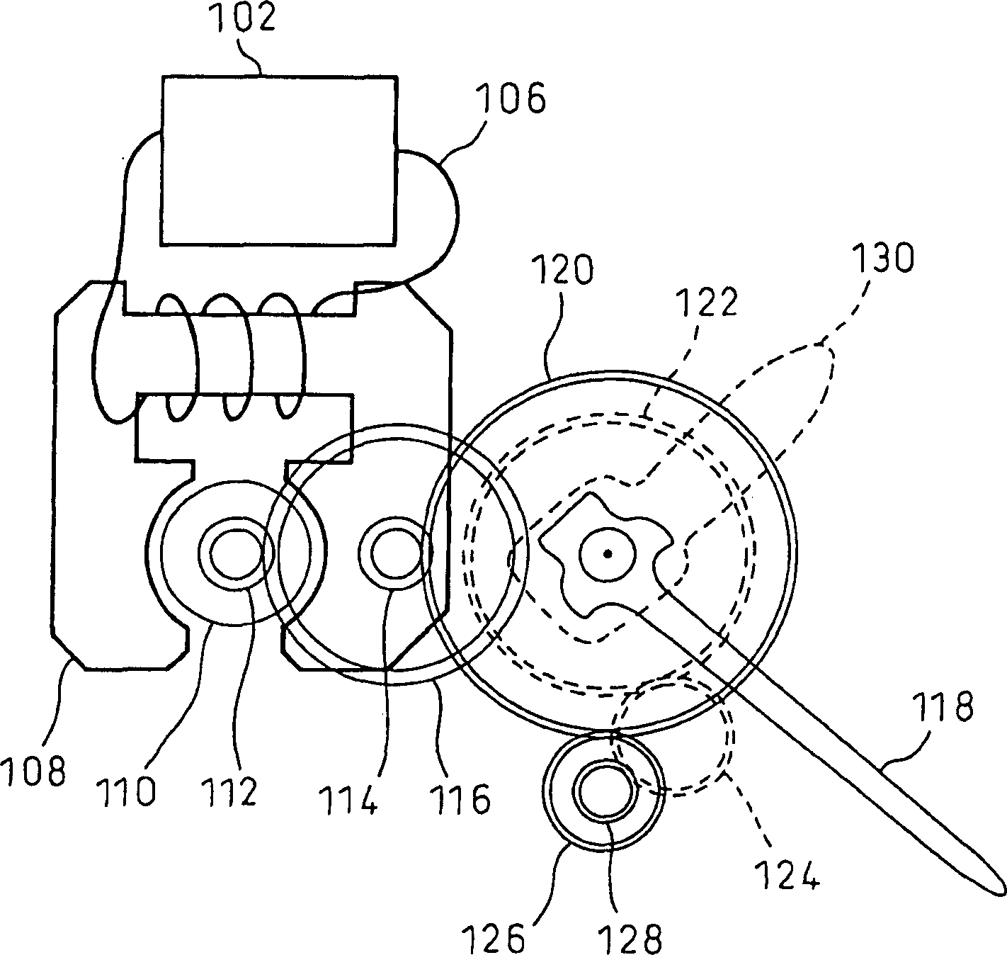
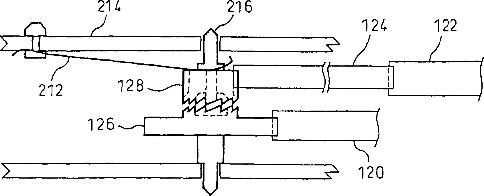
[0061] Figure 7 It is a block diagram showing the transmission path of the watch wheel train of the present invention, and is a diagram showing the outline of the diverging and merging mechanism of the present invention. Figure 7 The compositional feature of the clock is that a branch mechanism and a converging mechanism of the wheel train are set in the transmission path of the second, minute, hour, and day of the mechanical wheel train of the clock. In the present invention, the gear train has two transmission paths with different reduction ratios, and by switching them at any time, the action of the gear train for time keeping can be controlled in various ways. For example, a "normal drive mode" in which the second, minute, and hour hands are driven, and a "power-saving drive mode" in which only the minute and hour hands are driven are set. Switching between the normal drive mode and the power-saving drive mode is performed by switching the rotation direction of the moto...

Embodiment 3

[0084] Embodiments of the invention of the synchronization mechanism are described below. The synchronization mechanism described below can be used to synchronize the electric time counted by the electric timepiece ETK and the mechanical time counted by the mechanical timepiece MMK in the first and second embodiments described above.

[0085]In order to synchronize the electric chronograph time of the electric chronograph ETK with the mechanical chronograph time of the mechanical chronograph MMK, various methods can be used. The method with the least load on manufacturing is to pull out the crown for a while to stop the clock when the second hand reaches the full minute position (=0 second), and reset both the electric timing ETK and the electric mechanical time keeping timer MTK to 0, so that Tet Synchronized with Tmt at the second level. In the future, as long as the clock is not stopped, the ETK does not malfunction or lose synchronization, and the synchronization can be m...


PUM


Abstract

A time keeping device of an electric timepiece comprising one motor that can rotate in the forward direction and the reverse direction, a branch mechanism, and a plurality of wheel trains that are branched by the branch mechanism, wherein the motor is rotated in the forward direction to drive one wheel train thereby to carry out a mechanical display, and is rotated in the reverse direction to drive the other wheel train thereby to carry out another mechanical display. The time keeping device further comprises a merge mechanism in addition to the branch mechanism, and a plurality of wheel trains that are branched by the branch mechanism and are merged by the merge mechanism. The motor is rotated in the forward direction to drive one wheel train thereby to carry out a mechanical display, and is rotated in the reverse direction to drive the other wheel train thereby to carry out another mechanical display.

Description

technical field [0001] The present invention relates to a timekeeping mechanism of an electric clock that uses a motor capable of forward and reverse movement, and can perform different actions on a plurality of wheel trains with one motor. Background technique [0002] Battery watches are manufactured and sold with disposable batteries such as silver or lithium batteries. Quartz crystal watches that keep time accurately for 1 to 3 years without winding are widely popular because they are easy to carry and cheap. However, the country has regulations on places to sell watch batteries, and the price of batteries and replacement fees are also high. For this reason, when the battery is consumed, the clock is stopped because the battery cannot be replaced. In addition, the disposal of consumable batteries leads to the disposal of precious metal resources or the disposal of toxic mercury, which is harmful to the global environment. The recycling of used batteries requires a lot...

Claims


Application Information

Patent Timeline
Patent Type & Authority Applications(China)
IPC IPC(8): G04B11/02G04B13/00G04C3/00
CPCG04C3/008G04B13/00G04B11/024
Inventor 诸川滋岩仓良树野崎孝明矢野敬和福田正己坂本和男
Owner CITIZEN WATCH CO LTD
Why Eureka
Try Eureka