Wheel rail vibration electricity generating and energy storing system

A technology of vibration power generation and energy storage system, applied in current collectors, electromechanical devices, electric vehicles, etc., can solve the problems of low practical application, large space required, and low life expectancy.

Active Publication Date: 2015-08-26
苏州市振渭城镇建设发展有限公司
View PDF8 Cites 16 Cited by
  • Summary
  • Abstract
  • Description
  • Claims
  • Application Information

AI Technical Summary

Problems solved by technology

[0006] The device involved in the above scheme uses the laid piezoelectric element to collect vibration energy, which has the following defects: firstly, the piezoelectric element has low power generation efficiency, and the power is at the microwatt level, which has little effect on practical application; secondly, the device needs to be Before laying the wheel and rail, it is installed under the sleepers, which requires a large space and is likely to cause hidden dangers to railway safety; moreover, the piezoelectric element laid under the wheel and rail sleepers has a shorter service life than the mechanical structure, and is more susceptible to external physical factors. High maintenance and maintenance costs
[0008] The above scheme is to use the vibration brought by the train passing through the device to generate electricity, which has the following defects: first, the vibration is transmitted through the tractor and the blades, which cannot effectively integrate and convert the up and down flying line vibration brought by the train into a single unit. The rotational torque in the direction is output to the generator, resulting in low efficiency; at the same time, the blade structure is fragile, and the device as a whole is easily damaged, resulting in poor stability of the above structure

Method used


Image

  • Wheel rail vibration electricity generating and energy storing system
  • Wheel rail vibration electricity generating and energy storing system
  • Wheel rail vibration electricity generating and energy storing system

Examples


Embodiment Construction

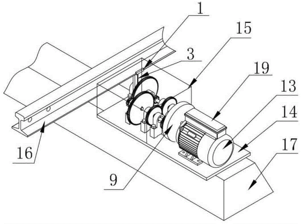
[0026] Such as figure 1As shown, the wheel-rail vibration power generation and energy storage system in this embodiment includes a clamping structure 1, a rack 3, a gear train structure 15, a generator 13 (in this embodiment, a DC generator is selected), a storage device 19, base plate 14. One end of the clamping structure 1 is fixedly connected to the rack 3, and the other end can be clamped on the bottom of the wheel rail 16; the rack 3 meshes with the gear train structure 15, and the gear train structure 15 is axially connected to the generator 13, and the generator 13 is electrically connected to The storage device 19 , the wheel train structure 15 and the generator 13 are installed on the base plate 14 , and the base plate 14 is fixed on the top of the sleeper rail 17 .

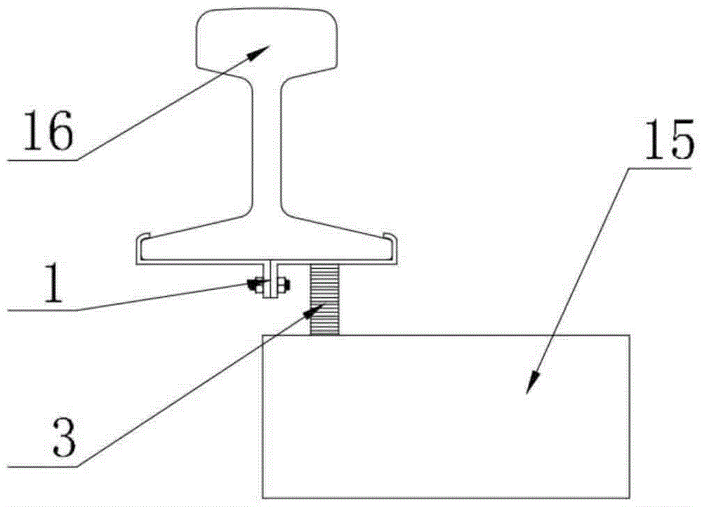
[0027] In the above-mentioned wheel-rail vibration power generation and energy storage system, the connection mode of the clamping device 1, the rack 3, the wheel train 15 and the wheel-rail 16 is as fo...


PUM


Abstract

The invention provides a wheel rail electricity generating and energy storing system adopting rack and gear transmission. In order to achieve the purpose, the wheel rail vibration electricity generating and energy storing system comprises a clamping structure, a rack, a wheel train structure, a generator, a storage device and a bottom plate. The wheel rail vibration electricity generating and energy storing system is characterized in that the clamping structure clamp the lower portion of a wheel rail, the rack is fixedly connected to the clamping structure, the rack is meshed with the wheel train structure, a one-way transmission selection device is arranged in the wheel train structure, an output shaft of the wheel train is connected with the generator, the generator is electrically connected with a storage device, and the system is fixed to a bottom plate.

Description

technical field [0001] The invention relates to a wheel-rail vibration power generation and energy storage system, in particular to a mechanical energy power generation and storage system utilizing trains passing through the wheel-rail. Background technique [0002] The energy crisis is one of the most concerned issues in the world today. [0003] my country is one of the few major railway countries in the world, with a total railway mileage of more than 100,000 kilometers, ranking first in the world. As we all know, the train will cause nonlinear vibration of the wheel rail and sleeper rail during the running process. These vibrations contain a large amount of mechanical energy. Through the energy recovery and collection device, we can convert it into usable electrical energy. These collected The generated energy can be used for auxiliary equipment at level crossings of roads and railways, emergency power supply, and small lighting power supply such as small platforms in o...

Claims


Application Information

Patent Timeline
Patent Type & Authority Applications(China)
IPC IPC(8): F03G7/08H02K7/18H02K7/116H02J7/32
CPCF03G7/08H02K7/025H02K7/10H02K7/11H02K7/116
Inventor 张祖涛张兴田张仁贤朱亚男张琦涛杨越南佳俊白呼和
Owner 苏州市振渭城镇建设发展有限公司
Why Eureka
Try Eureka