[0019] Hereinafter, embodiments of the compressor mounting device of the present invention will be described in detail with reference to the accompanying drawings.
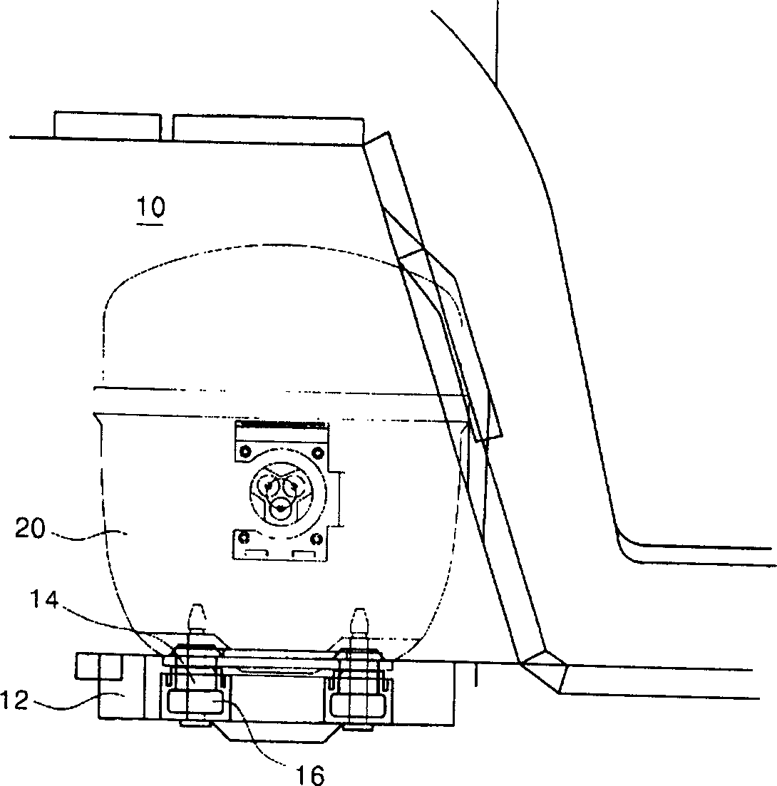
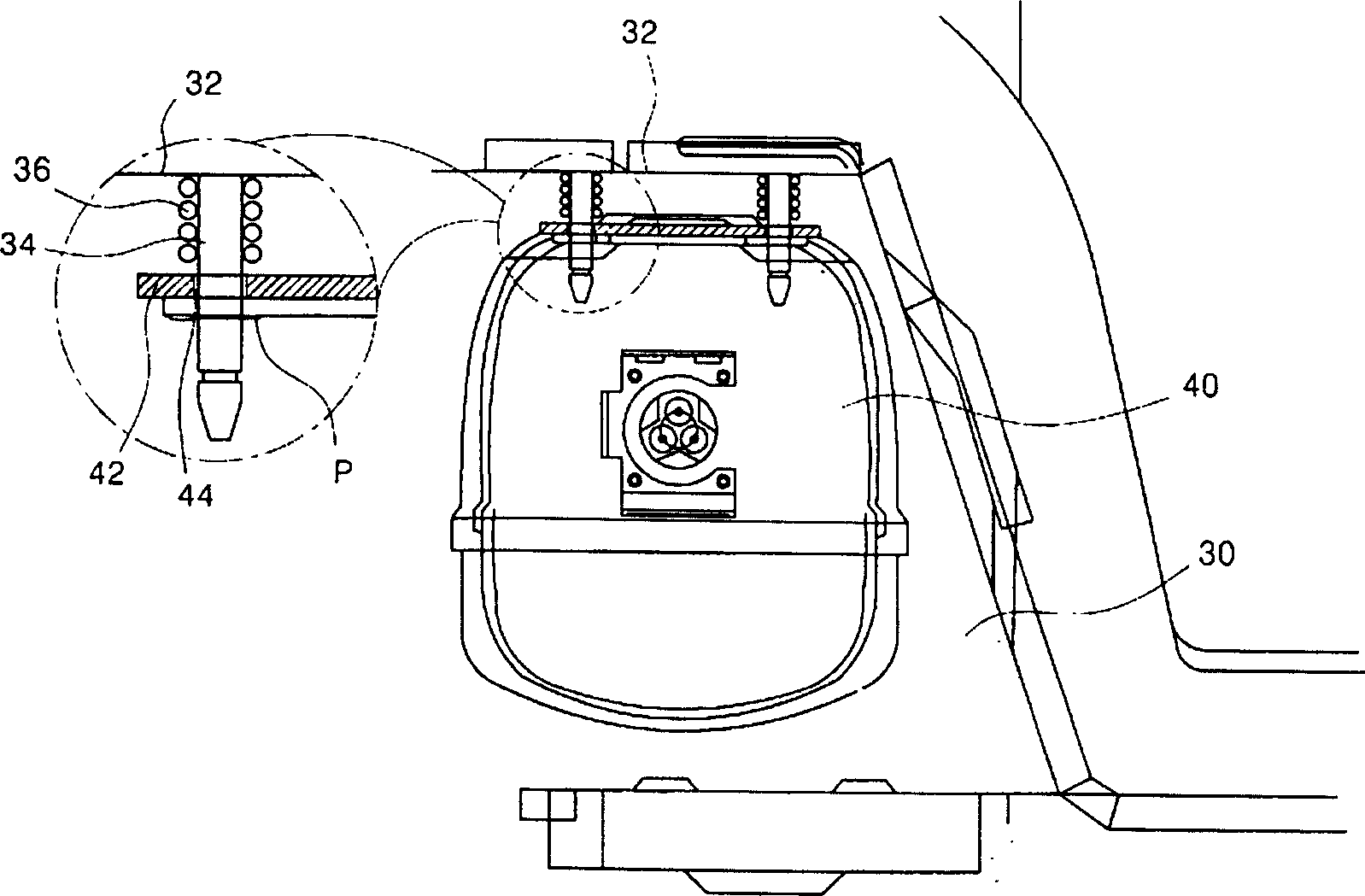
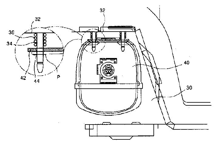
[0020] figure 2 It shows a schematic cross-sectional view of the compressor installation structure of the present invention. Such as figure 2 As shown, in the present invention, the compressor 40 is hung on the upper surface 32 of the machine room 30.
[0021] As described above, by suspending the compressor 40 on the upper surface 32 of the machine room 30, the vibration generated by the compressor 40 can be fundamentally prevented from being transmitted to the bottom surface of the refrigerator, so it is useful for reducing vibration and noise. Is the most effective.
[0022] Specific embodiments are described in detail below. As shown in the figure, the upper end surface of the compressor 40 is provided with a mounting plate 42 for mounting the compressor. The area of the mounting plate 42 is larger than that of the upper surface of the compressor 40, and the compressor and the mounting plate can be fixed by welding or other methods.
[0023] In addition, a plurality of mounting holes 44 are formed on the above-mentioned mounting plate 42. A mounting shaft 34 is inserted into the mounting hole 44, and the mounting shaft 34 is formed downward from the upper surface 32. A coupling pin P is horizontally inserted at the lower end of the above-mentioned mounting shaft 34. The coupling pin P of the mounting shaft 34 inserted into the mounting hole 44 of the mounting plate 42 of the compressor 40 can support the lower end of the mounting plate of the compressor in a suspended state.
[0024] In addition, it is preferable to provide a material such as vibration absorbing rubber that can absorb vibration between the coupling pin P and the mounting plate 42.
[0025] Among them, in a state where the mounting shaft 34 is inserted into the mounting hole 44, the mounting plate 42 can be suspended from the lower end of the mounting shaft 34 in many embodiments. For example, the lower end of the mounting shaft 34 inserted into the mounting hole 44 is coupled with a nut to support the lower end of the mounting plate 42 of the compressor in the hanging state.
[0026] In addition, a flange member may be formed at the lower part of the mounting shaft 34 inserted into the mounting hole 44, and the flange member may be fixed by a method such as fixing a separate member by welding or the like, and the flange portion should be extended radially It is formed to prevent the mounting shaft 34 from falling off the mounting hole 44.
[0027] As described above, there can be many implementations of the supporting structure for preventing the mounting plate 42 inserted on the mounting shaft 34 from falling downward. The mounting plate 42 is supported on the mounting shaft 34, and the compressor 40 can be lifted. It is supported by being hung on the upper surface 32 of the machine room 30 described above.
[0028] In addition, a spring 36 is provided between the upper surface 32 of the machine room 30 and the mounting plate 42. The above-mentioned spring 36 can absorb vibration generated when the compressor vibrates.
[0029] Hereinafter, the overall function of the compressor mounting device of the present invention having the above-mentioned structure will be described in detail.
[0030] As described above, when the compressor 40 supported on the upper surface 32 is driven, the vibration and noise generated by it cannot be transmitted to at least the bottom surface of the machine room where the compressor chassis is provided. Therefore, the vibration and noise of the entire refrigerator caused by the vibration of the bottom surface of the plate-shaped machine room are prevented.
[0031] In addition, the vibration and noise generated by the compressor 40 are first absorbed by the spring 36. Therefore, part of the vibration and noise generated by the compressor 40 is transmitted to the main body of the refrigerator through the upper surface 32 of the machine room 30. However, the vibration transmitted to the main body of the refrigerator through the above-mentioned path will be absorbed again by the insulating material layer of the refrigerator. In other words, since the heat insulating material layer of the refrigerator is formed by the foam filled between the outer box and the inner box, the foam not only has a heat insulating function, but also has a function of absorbing vibration. Therefore, vibration and noise can be absorbed by the insulation material layer of the refrigerator body. The above structure is different from the structure in which the vibration is transmitted to the bottom surface of the refrigerator in the prior art. That is to say, since the bottom surface in the prior art does not have a structure that can absorb vibration and noise, that is, there is almost no vibration-absorbing structure on the bottom surface of the refrigerator or the compressor chassis, so when the vibration of the compressor is When transmitted to the bottom surface of the refrigerator, it is transmitted almost intact to the outside world.
[0032] However, in the present invention, the vibration generated on the compressor 40 is first absorbed by the above-mentioned spring, and then is effectively absorbed by the insulating material layer of the refrigerator body.
[0033] In the present invention, the transmission of vibration generated in the hanging state of the compressor is obviously less than that of the prior art. On the basis of the above hanging method, the vibration and noise can be absorbed more effectively by the spring and the vibration damping structure of the heat insulating material layer of the body.
[0034] Through the above description of the present invention, it can be understood that the basic technical idea of the present invention is to install the compressor on the upper surface 32 of the machine room.
[0035] So far, although the detailed description is centered on the embodiments of the present invention, a person with general knowledge in the technical field of the present invention can propose many modifications within the scope of the basic technical idea of the present invention. The basic technical idea of the present invention is embodied in the scope of the claims, and all differences within the equivalent scope should be interpreted as belonging to the scope of the present invention.