Optical disk rallet

A technology of discs and trays, used in data recording, packaging, instruments, etc.

Inactive Publication Date: 2004-02-18
郑吉浃
View PDF0 Cites 1 Cited by
  • Summary
  • Abstract
  • Description
  • Claims
  • Application Information

AI Technical Summary

Problems solved by technology

[0007] The present invention solves the problems in the existing clip-on open disc case due to other specific features.

Method used


Image

  • Optical disk rallet
  • Optical disk rallet
  • Optical disk rallet

Examples


Embodiment Construction

[0019] Hereinafter, preferred embodiments of the present invention will be described with reference to the drawings. In the drawings, the same reference numerals are assigned to the same parts and descriptions.

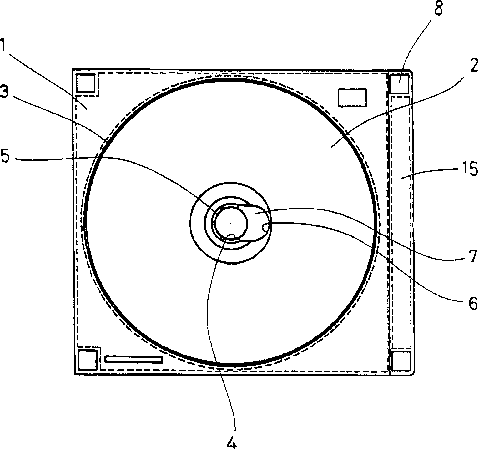
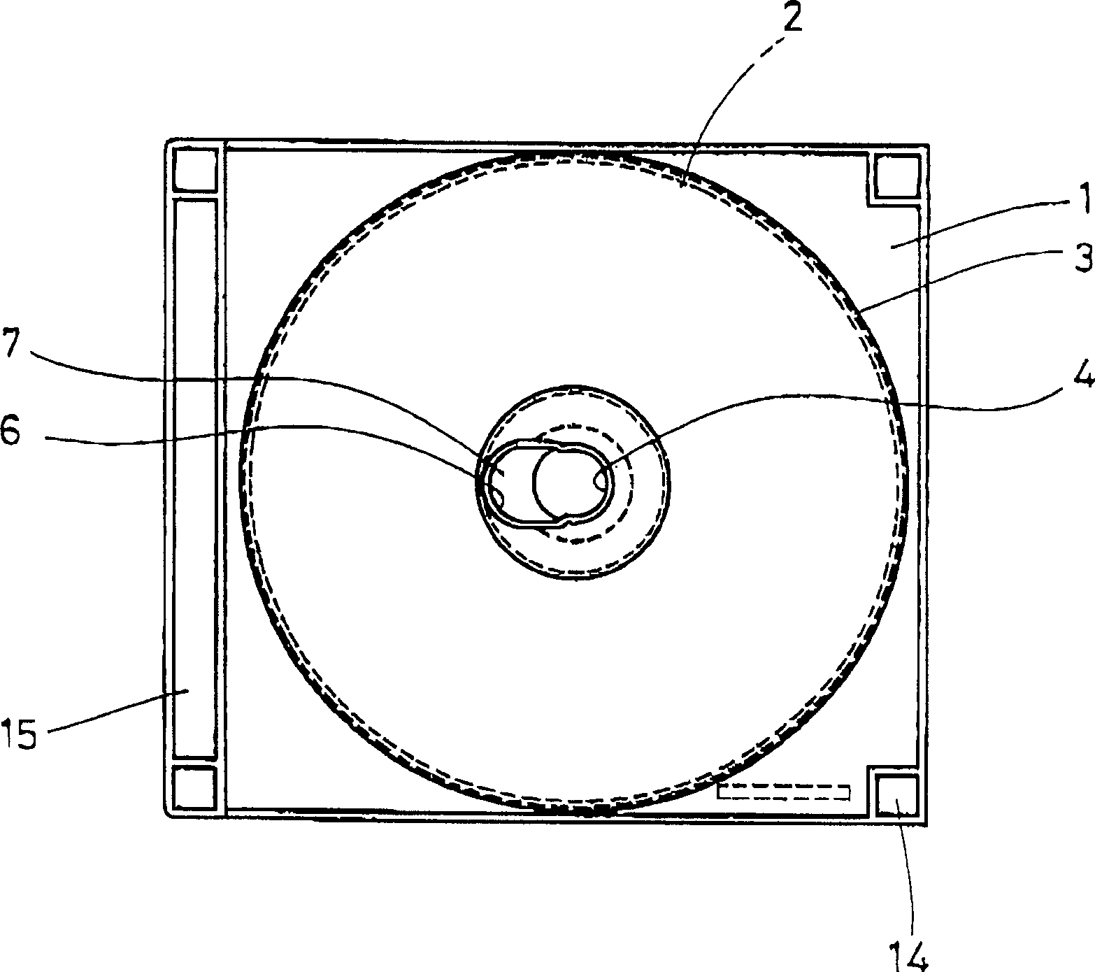
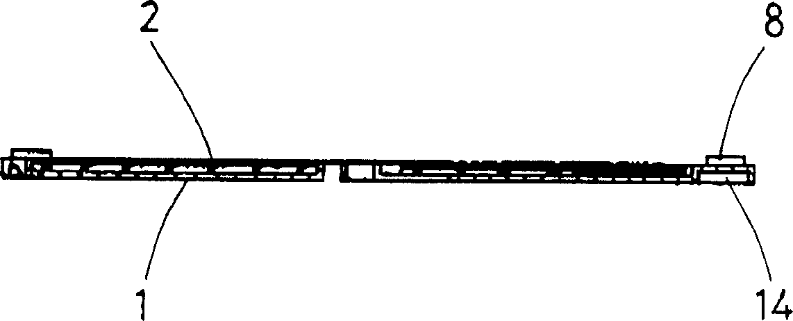
[0020] refer to figure 1 , is a plan view showing a state in which an optical disc is accommodated in an optical disc tray according to an embodiment of the present invention. The disc tray of the present invention includes a disc clamping plate 1 . A circular recess 3 for accommodating an optical disc 2 is formed on the upper side of the disc holder 1 . A hole 4 is formed in the center portion of the disc holder 1 described above. On the inner edge of the disc holder 1 where the above-mentioned hole 4 is formed, clamping pins 5 are formed spaced apart in the circumferential direction. The hole 4 is formed adjacent to and communicates with the release opening 6 .

[0021] The disc holder 1 of the present invention is made of a suitable material, for example plast...


PUM


Abstract

Disclosed is a housing device for compact disks. The housing device includes stackable and bookbindable CD trays, each of which has clip pegs with a hole defined at a center portion of each CD tray. A compact disc can be released by pushing a non-data portion thereof through a release opening defined adjoining the hole in each CD tray. An adhesive tape can be affixed to one side ends of the CD trays and a lock band can be attached to the other side ends of the CD trays, to bookbind the CD trays together.

Description

technical field [0001] The present invention relates to a bundled optical disc tray capable of storing optical discs in an orderly manner. Background technique [0002] An optical disc is a device that receives recorded data signals along tiny tracks on a plastic floppy disk through laser beam technology, and is generally called a CD. Not only video images, audio signals, etc. but accurate storage systems for all types of data have been rapidly improved since Philips and Sony first introduced prototypes in the late seventies. [0003] However, despite the recognized advantages, there are some problems with storing discs in the case. As a result, the clip-on open box used at first still dominates the market. Here, since it is inherently difficult to bundle and store the clip-on open case, it is necessary to adopt another method. The clip-on open case is inconvenient for retrieval work, document storage, publishing, etc. Therefore, the box is sometimes replaced by other bu...

Claims


Application Information

Patent Timeline
IPC IPC(8): B65D85/57G11B23/02G11B23/03G11B33/04
CPCG11B33/045Y10S206/815G11B23/02
Inventor 郑吉浹
Owner 郑吉浃
Why Eureka
Try Eureka