Damping device, flat table device and exposuring device

A technology of an anti-vibration device and an exposure device, which is applied to a photo-engraving process exposure device, a microlithography exposure device, optics, etc., can solve the problem of the increase in the size of the voice coil motor and the increase in power consumption, the deterioration of the control accuracy of the exposure device, and the support object. OB deformation and other problems, to achieve the effect of small and lightweight vibration damping effect, good vibration damping effect

Inactive Publication Date: 2004-03-10
NIKON CORP
View PDF1 Cites 51 Cited by
  • Summary
  • Abstract
  • Description
  • Claims
  • Application Information

AI Technical Summary

Problems solved by technology

Especially in this structure, the rigidity in the direction of gravity is small and the rigidity in the horizontal direction and torsional direction is strong, so it is not possible to obtain a sufficient ground vibration attenuation effect, that is, a sufficient vibration isolation effect.
[0013] In the anti-vibration device 931, high response control can be realized by using a voice coil motor (voice coil motor) 974. However, in order to maintain a large-scale device such as an exposure device, in order to use three positions or four Each position supports a weight of about 10 tons, and each position supports a weight corresponding to a mass of about 3 tons, and must move up and down. As a voice coil motor, a very large thrust is required
Therefore, the size of the voice coil motor (voice coil motor) itself will increase and the power consumption will increase.
[0014] Additionally, by Figure 17 (A), Figure 17 (B) It can be seen that in the conventional anti-vibration device, the position of the air cushion support structure and the position of the action point of the driving force of the voice coil motor (voice coil motor) deviate, so electromagnetic adjustment is performed at the same time When the internal pressure control of the air pressure chamber in the device and the position control of the object OB to be supported by the voice coil motor (voice coil motor) 974, the object OB to be supported will be deformed, and this becomes a problem for each part of the exposure device. Causes of Control Accuracy Deterioration

Method used


Image

  • Damping device, flat table device and exposuring device
  • Damping device, flat table device and exposuring device
  • Damping device, flat table device and exposuring device

Examples


Embodiment Construction

[0181] "First Embodiment"

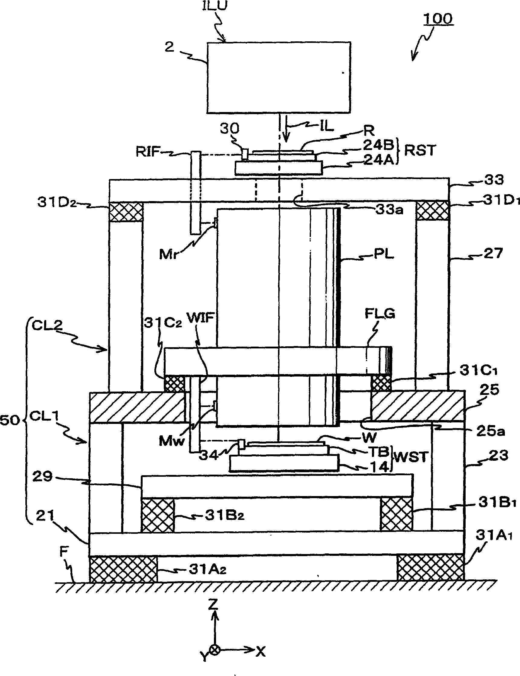
[0182] Below, according to Figure 1 to Figure 7 (B) The first embodiment of the present invention will be described. figure 1 The schematic diagram shows the overall configuration of the exposure apparatus 100 according to the first embodiment. This exposure apparatus 100 moves the grating R as a mask and the wafer W as a photosensitive object synchronously in one-dimensional direction, and transfers the circuit pattern formed on the grating R onto the wafer W through the projection optical system PL. A scanning exposure device of a step-and-scan method in an imaging area is a so-called scanning stepper exposure device.

[0183] The exposure apparatus 100 is provided with an illumination unit ILU for illuminating a rectangular slit-shaped illumination area on the grating R with uniform illuminance by means of illumination light for exposure as an energy beam (hereinafter simply referred to as "illumination light"), and as a holding grating. The...


PUM


Abstract

In order to remove vibration or improve a vibration control effect, and achieve device size reduction, an adjusting device is provided in which a weight of a support target object is supported by a pressure of an internal gas of a first chamber gas via a holding member and which adjusts a position in a gravity direction of the holding member by driving a movable member which changes an internal volume of the first gas chamber by changing an internal volume of a second gas chamber based on a state change of at least one of first and second gas chambers. Because of this, when the holding member is displaced in the gravity direction because of the vibration or the like, as the movable member is driven by the adjusting device, the holding member is maintained at an original position. Additionally, the movable member does not contact the support target object, so it does not directly deform the support target object, and the support target object is only driven by the change of the internal volume of the gas chambers; thus, even if the rigidity of the gas within the first gas chamber is high, there will be no problem regarding transmission of vibrations.

Description

technical field [0001] The present invention relates to an anti-vibration device, a platform device, and an exposure device, and more specifically relates to an anti-vibration device that suppresses vibration while holding an object, and a table device and an exposure device including the anti-vibration device. Background technique [0002] For a long time, in the etching process used to manufacture semiconductor components and liquid crystal display components, the pattern formed on the mask or grating (hereinafter collectively referred to as “grating”) is mainly used to apply photoresist, etc. through the projection optical system. A step-and-repeat reduction projection exposure device (so-called step-and-shift exposure device) that performs transfer on substrates such as wafers or glass plates (hereinafter collectively referred to as "wafers"), and improved step-and-shift exposure devices A stepping type projection exposure apparatus such as a step and scan type scanning ...

Claims


Application Information

Patent Timeline
Patent Type & Authority Applications(China)
IPC IPC(8): G03F7/22F16F15/027F16F15/03G03F7/20H01L21/027
CPCF16F15/03G03F7/709F16F15/0275G03F7/70833H01L21/027
Inventor 西健尔
Owner NIKON CORP
Why Eureka
Try Eureka