Touch-panel input device having a function for providing vibration and method for providing vibration in response to input operation

a technology of input device and function, which is applied in the direction of instruments, computing, electric digital data processing, etc., can solve the problems of touch panel vibrating, vibration corresponding to the operation of the switch cannot be smoothly transmitted to the user, and the speaker cannot distinguish between the vibration of force feedback, so as to prevent vibrations representing force feedback, smooth input, and easy change

Active Publication Date: 2006-02-02
ALPINE ELECTRONICS INC
View PDF4 Cites 52 Cited by
  • Summary
  • Abstract
  • Description
  • Claims
  • Application Information

AI Technical Summary

Benefits of technology

[0020] In the touch-panel input device according to the first aspect of the present invention, for example, when the operator brings his or her finger close to the touch panel to operate the touch panel, the sensor detects this operation. Then, the operation mode is automatically changed from the speaker mode or the microphone mode to the input operation mode. Thus, the operation mode can be readily changed from the speaker mode or the microphone mode to the input operation mode without operating a hardware key other than the touch panel even while the touch panel is used as a speaker or a microphone. Accordingly, vibrations representing force feedback can be smoothly provided to the operator without a complicated operation even while the touch panel is used as a speaker. Moreover, vibrations representing force feedback can be prevented from being erroneously transmitted as voice input without a complicated operation even while the touch panel is used as a microphone.
[0021] In the touch-panel input device according to the second aspect of the present invention, for example, when the operator brings his or her finger close to the touch panel to operate the touch panel, the sensor detects this operation. Then, the magnitude of the vibrations of the touch panel for providing force feedback is adjusted so as to be larger than that for producing the sounds. Thus, the vibrations representing force feedback can be smoothly provided to the operator without operating a hardware key other than the touch panel even while the touch panel is used as a speaker.
[0022] In the touch-panel input device according to the third aspect of the present invention, for example, when the operator brings his or her finger close to the touch panel to operate the touch panel, the sensor detects this operation. Then, the frequency band of vibrations for force feedback is removed from the frequency band of vibrations of the sounds to be produced. Thus, the vibrations of the touch panel for force feedback are clearly distinguished from the vibrations of the touch panel for producing the sounds. Accordingly, the vibrations for force feedback can be smoothly provided to the operator without operating a hardware key other than the touch panel even while the touch panel is used as a speaker.

Problems solved by technology

In this case, when this touch panel is used as a speaker by vibrating the touch panel and the user operates a switch displayed on the touch panel at the same time, vibrations of the speaker cannot be distinguished from those of force feedback.
Thus, vibrations corresponding to the operation of the switch cannot be smoothly transmitted to the user.
In this case, when the touch panel is used as a microphone and the user operates a switch displayed on the touch panel at the same time, the touch panel may vibrate in response to the operation of the switch and the vibrations may be erroneously transmitted as voice input.
Thus, the operation is disadvantageously complicated.

Method used


Image

  • Touch-panel input device having a function for providing vibration and method for providing vibration in response to input operation
  • Touch-panel input device having a function for providing vibration and method for providing vibration in response to input operation
  • Touch-panel input device having a function for providing vibration and method for providing vibration in response to input operation

Examples


first embodiment

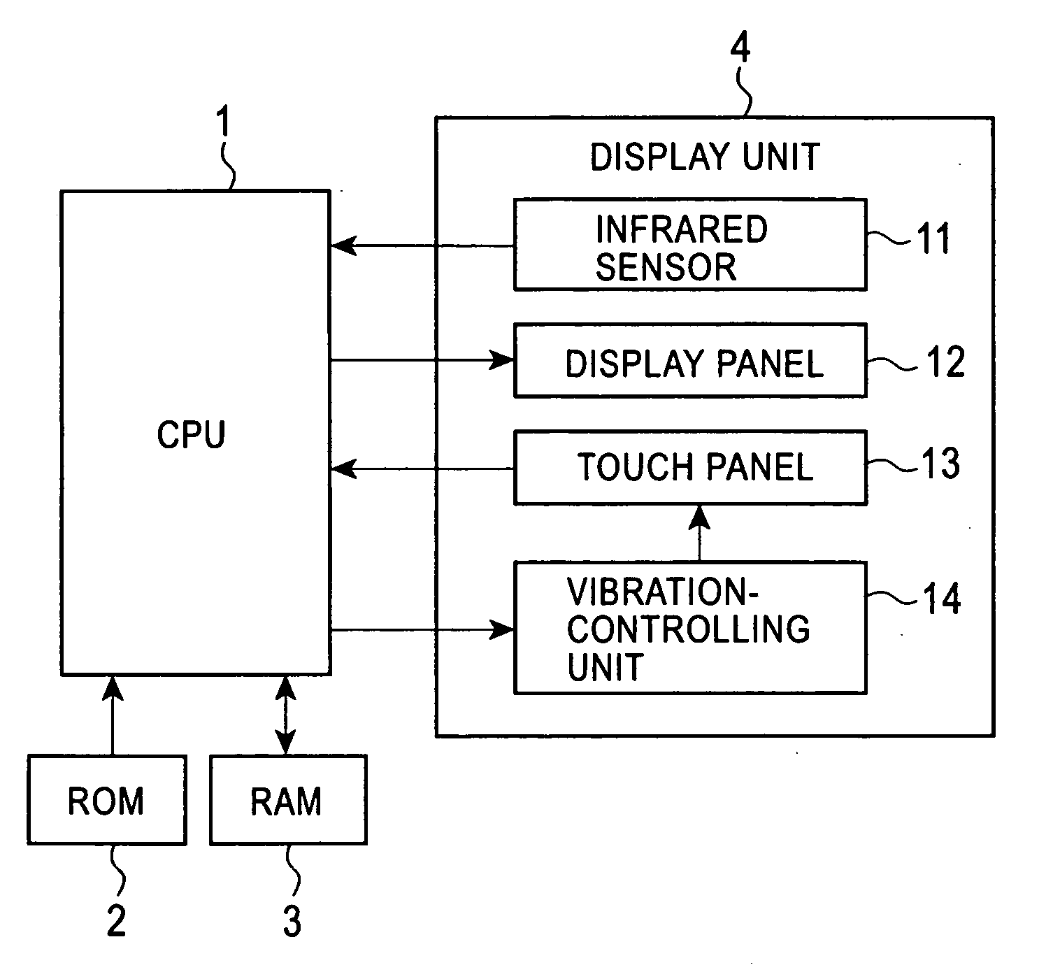
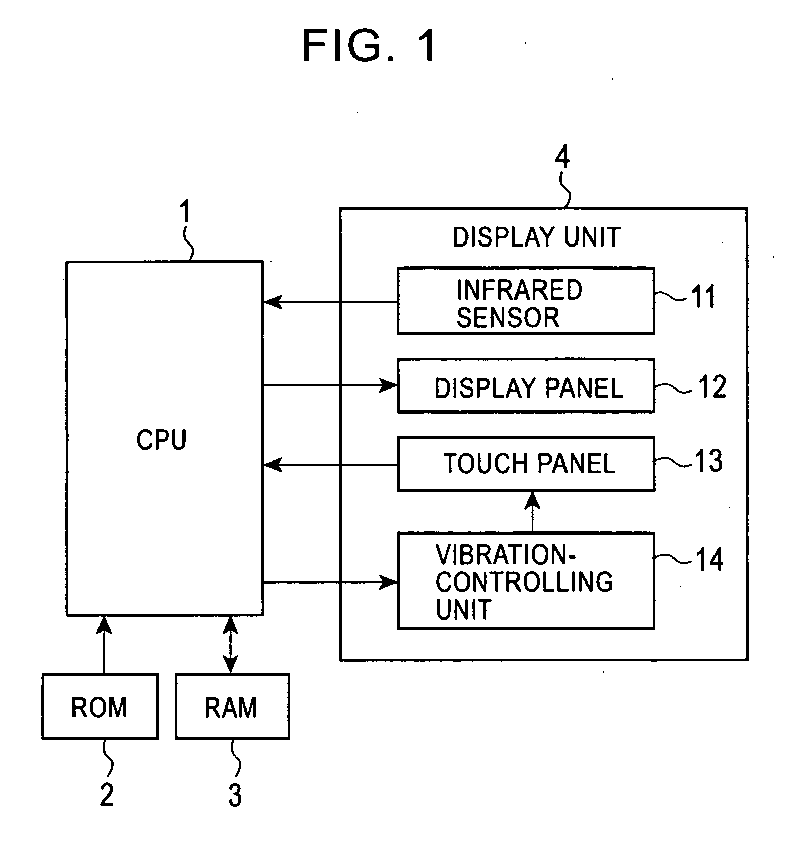
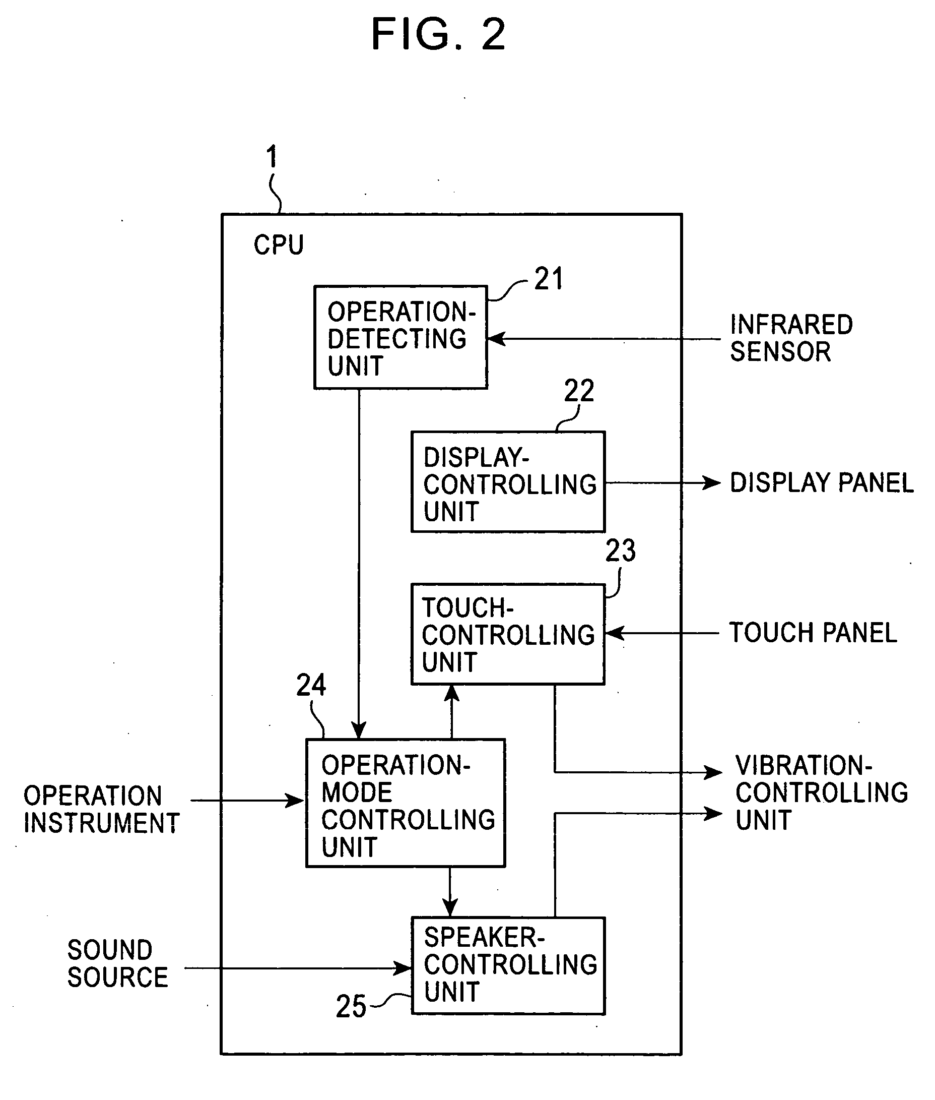
[0035] A first embodiment according to the present invention will now be described with reference to the drawings. FIG. 1 is a block diagram illustrating the structure of a typical touch-panel input device having a function for providing vibrations according to the FIG. 2 is a block diagram illustrating the structure of a typical CPU 1 shown in FIG. 1. FIGS. 3A and 3B illustrate a typical layout of an infrared sensor 11 shown in FIG. 1.

[0036] As shown in FIG. 1, the touch-panel input device includes the CPU 1, a ROM 2, a RAM 3, and a display unit 4. The display unit 4 includes the infrared sensor 11, a display panel 12, a touch panel 13, and a vibration-controlling unit 14.

[0037] The CPU 1 controls the overall process of the touch-panel input device. This control process will be described below with reference to FIG. 2. The ROM 2 stores programs performing various types of processes on the CPU 1. The RAM 3 temporarily stores intermediate data and output data that are generated in ...

second embodiment

[0060] A second embodiment according to the present invention will now be described with reference to the drawings. The structure of a touch-panel input device having a function for providing vibrations according to the second embodiment is the same as that shown in FIG. 1. FIG. 6 is a block diagram illustrating the structure of a typical CPU 1 according to the The layout of an infrared sensor 11 according to the second embodiment is the same as that shown in FIGS. 3A and 3B.

[0061] As shown in FIG. 6, the CPU 1 according to the second embodiment includes an operation-detecting unit 21, a display-controlling unit 22, a touch-controlling unit 23, an operation-mode controlling unit 26, and a microphone-controlling unit 27. Since the structure of the CPU 1 is the same as that shown in FIG. 2 except for the operation-mode controlling unit 26 and the microphone-controlling unit 27, a duplicated description is omitted.

[0062] A touch panel 13 according to the second embodiment has the fol...

third embodiment

[0077] As shown in FIG. 9, the CPU 1 includes an operation-detecting unit 21, a display-controlling unit 22, a touch-controlling unit 23, a speaker-controlling unit 25, and a volume-adjusting unit 28. Since the structure of the CPU 1 is the same as that shown in FIG. 2 except for the volume-adjusting unit 28, a duplicated description is omitted.

[0078] In the third embodiment, there is no switching operation between the input operation mode (the FFB mode) and the speaker mode described above. A vibration-controlling unit 14 according to the third embodiment controls both vibrations of a touch panel 13 for producing sounds as a speaker and vibrations of the touch panel 13 for providing force feedback. The vibration-controlling unit 14 vibrates the touch panel 13 upon detecting a user's touch on the touch panel 13, and vibrates the touch panel 13 at a frequency corresponding to sounds to be produced when the touch panel 13 is used as a speaker.

[0079] The volume-adjusting unit 28 adju...


PUM


Abstract

A touch-panel input device having a function for providing vibrations includes a touch panel receiving an operation on an operation item on a display panel, a vibration-controlling unit vibrating the touch panel, an operation detector detecting an operation on the touch panel, and an operation-mode controlling unit setting an operation mode of the touch panel to an input operation mode for vibrating the touch panel upon detecting a touch on the touch panel, or either a speaker mode for vibrating the touch panel to produce sounds or a microphone mode for allowing voice input by transmitting vibrations generated on the touch panel when the operator speaks to the touch panel. The operation-mode controlling unit changes the operation mode to the input operation mode when the operation mode is set to the speaker mode or the microphone mode upon detecting an operation on the touch panel.

Description

BACKGROUND OF THE INVENTION [0001] 1. Field of the Invention [0002] The present invention relates to touch-panel input devices having functions for providing vibrations and methods for providing vibrations in response to input operations, and more particularly to an input device having a force-feedback (FFB) function for providing vibrations to a user when the user operates a touch panel. [0003] 2. Description of the Related Art [0004] A touch-panel input device A touch-panel input device including a panel-shaped input operation unit on the surface of a liquid crystal display is known. In Japanese Unexamined Patent Application Publication No. 8-221173, a touch-panel input device is disclosed. This touch-panel input device has a function for providing vibrations to an operator through a vibrator when the operator touches a switch displayed on a screen of a touch panel to inform the operator of, for example, a position and the type of the switch, i.e., an FFB function. Hereinafter, th...

Claims


Application Information

Patent Timeline
Patent Type & Authority Applications(United States)
IPC IPC(8): G09G5/00
CPCG06F3/016G06F3/0416H04M2250/22H04M1/6033H04M2250/12G06F3/0421
Inventor SHIGA, MASAYOSHI
Owner ALPINE ELECTRONICS INC
Why Eureka
Try Eureka