Injection moulding method for stylus

A technology of stylus and pen body, which is applied in the direction of coating, etc., can solve the problems of high mold cost, difficult positioning of stylus, unreasonable ratio of input and output, etc.

Inactive Publication Date: 2004-03-31
MITAC COMP (SHUN DE) LTD
View PDF0 Cites 1 Cited by
  • Summary
  • Abstract
  • Description
  • Claims
  • Application Information

AI Technical Summary

Problems solved by technology

[0002] Most PDA manufacturers generally use a set of main injection molds to inject the touch pen at one time during the injection molding process of the touch pen. Although the injection molding process of this method is simple, the injected touch pen is easy. Bending occurs, making it difficult to guarantee its

Method used


Image

  • Injection moulding method for stylus
  • Injection moulding method for stylus
  • Injection moulding method for stylus

Examples


Embodiment Construction

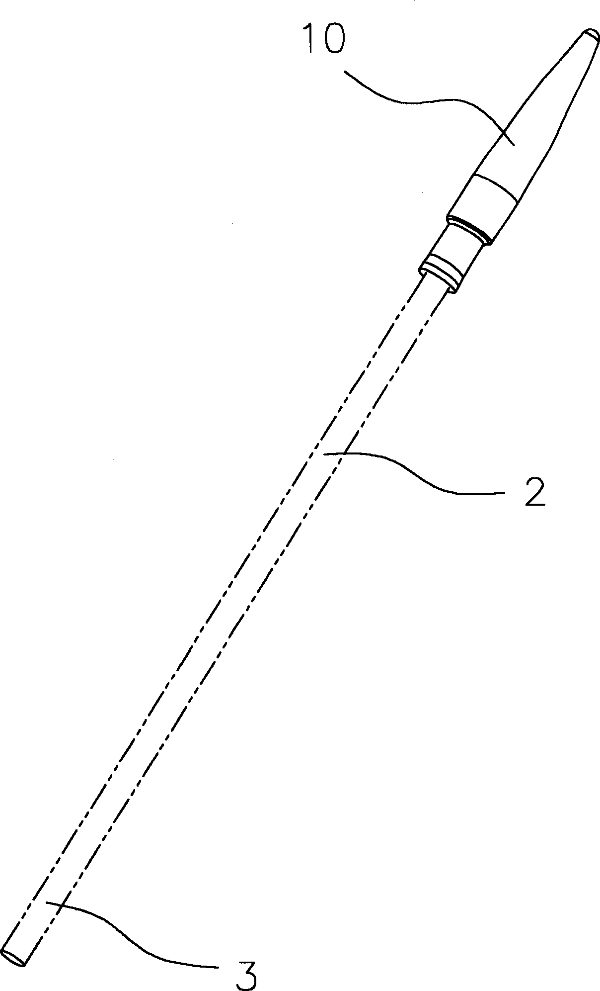
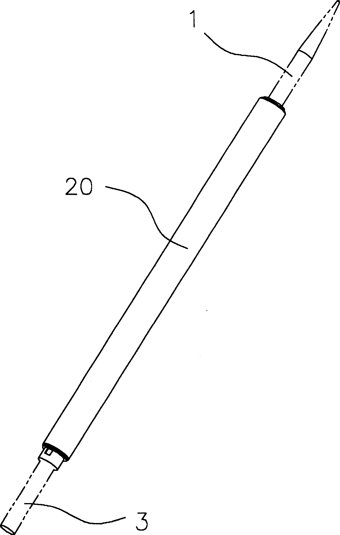
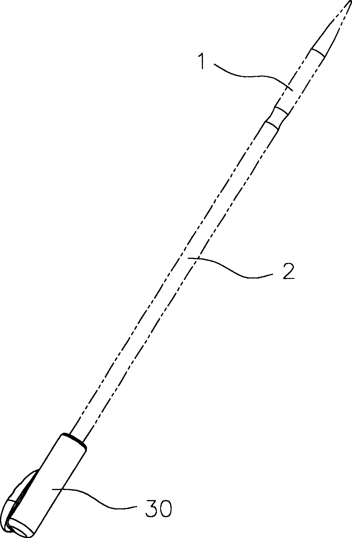
[0020] see Figure 1 to Figure 3 As shown, it is a schematic diagram of the injection sequence of a manufacturing method of a stylus for a handheld computer disclosed by the present invention. During the process of injecting the stylus, the inner pen body is sequentially placed into the corresponding main injection mold. Create the fixing tool described above to clamp and fix the stylus, and shoot out the contact end 10, the middle section 20, and the buckle end 30 of the stylus in sequence, so that the plastic can completely cover the inner pen body to form an insulating outer pen Each part of the injection will cover the remaining filling point of the last time, so that only one filling hole is left when the injection molding is finally completed, and the finished product of the stylus is the finished product after the filling mouth is rested and deburred.

[0021] see Figure 4 , 4A , 4B, and 4C are schematic diagrams of the structure of the main fixing tool for the injec...


PUM


Abstract

The invention discloses an injection moulding method for touch pens, in order to guarantee the moulding quality, the touch pen can be achieved through the injection moulding of three sets of dies, placing the inner pen units in sequence into the main spray dies. the tough pen is injected though the sequence of sequence end, intermediate section and the fastening end, which improves the quality oftouch pen injection. íí

Description

technical field [0001] The present invention mainly relates to the field of injection molding of touch pens used in electronic products, in particular to an injection molding method of touch pens (touch pen) used in electronic products and a fixing tool used in the injection molding process. Background of the invention [0002] Most PDA manufacturers generally use a set of main injection molds to inject the touch pen at one time during the injection molding process of the touch pen. Although the injection molding process of this method is simple, the injected touch pen is easy. Bending occurs, making it difficult to guarantee its straightness. At the same time, the cost of making this set of molds is very high, especially in occasions where the product output is not large, and there may even be an unreasonable ratio of input to output. In addition, during the injection molding process The positioning of the stylus is difficult to guarantee. [0003] Therefore, it is necessa...

Claims


Application Information

Patent Timeline
IPC IPC(8): B29C45/00
Inventor 周波
Owner MITAC COMP (SHUN DE) LTD
Why Eureka
Try Eureka