Magnetorheological fluid damp type dynamic vibration absorber and method of mounting thereof

A technology of dynamic vibration absorber and magnetorheological fluid, which is applied in the direction of shock absorber, etc., can solve problems such as not being able to achieve the best design effect, and achieve the effects of good development prospects, flexible operation, and good nonlinear vibration damping performance

Inactive Publication Date: 2004-03-31
TIANJIN UNIVERSITY OF TECHNOLOGY
View PDF0 Cites 17 Cited by
  • Summary
  • Abstract
  • Description
  • Claims
  • Application Information

AI Technical Summary

Problems solved by technology

Obviously, this approach cannot achieve the best design effect wheth

Method used


Image

  • Magnetorheological fluid damp type dynamic vibration absorber and method of mounting thereof
  • Magnetorheological fluid damp type dynamic vibration absorber and method of mounting thereof
  • Magnetorheological fluid damp type dynamic vibration absorber and method of mounting thereof

Examples


Embodiment

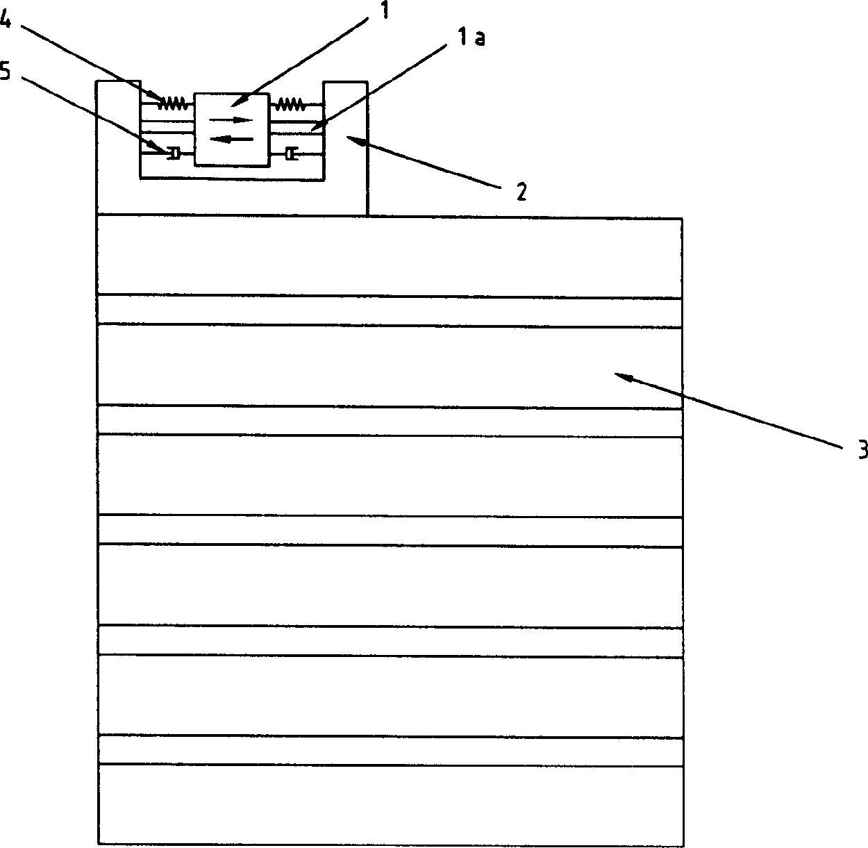
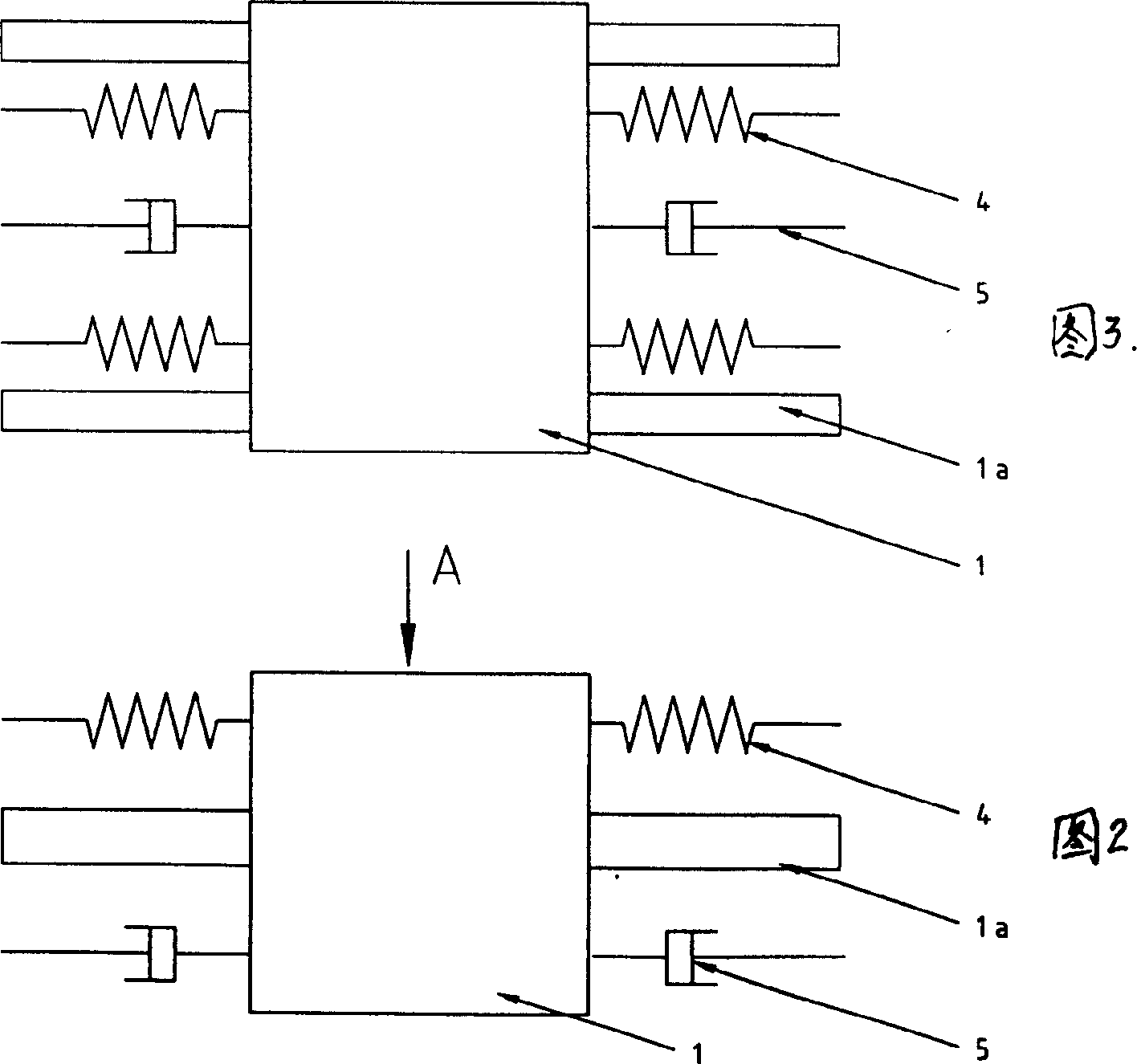
[0018] Embodiment: A magnetorheological fluid damping type dynamic shock absorber (see Fig. 1-3), is characterized in that it is made of linear motor 1 containing linear guide rail, support frame 2, magnetorheological fluid damper 5 and metal spring 4, the support frame 2 is a "concave" support including the bottom plate and the side wall, the linear guide rail 1a of the linear motor 1 is horizontally installed on the side walls at both ends of the support frame 2, and the two magneto-rheological fluid dampers The device 5 is installed between the side wall of the support frame 2 and the linear motor 1 and between the linear motor 1 and the side wall of another support frame 2, and the four metal springs 4 are also respectively installed on the side wall of the support frame 2 and the linear motor 1. And between the linear motor 1 and the side wall of another supporting frame 2 and parallel to the linear guide rail 1a of the linear motor 1 .

[0019] A method for installing a ...


PUM


Abstract

A magnetic flow variation damping type power-driven shock and vibration absorption device, comprising a linear electric motor having a straight guide, a straddle, a magnetic flow variation damping apparatus and a metal spring. The invention also discloses the process for mounting the device. The beneficial effect of the invention is, the active vibration damper possesses good non-linear damping vibration performance.

Description

(1) Technical field: [0001] The invention relates to a vibration damping device and an installation method applied to building structures and mechanical equipment, in particular to a magnetorheological fluid damping dynamic vibration absorber and an installation method. (two) background technology: [0002] According to the traditional design idea of ​​vibration reduction, the damping of ordinary vibration reduction system should not be too large. If only from the viewpoint of resonance control, it is hoped to increase the damping value of the system to reduce the resonance transfer rate and limit the resonance amplitude. However, from the perspective of pure vibration reduction, the increase of the damping value will reduce the vibration reduction effect. In the usual design methods, one is to keep the resonant frequency of the system away from the excitation frequency as much as possible to obtain a good vibration reduction design effect; the other is when the excitation ...

Claims


Application Information

Patent Timeline
IPC IPC(8): F16F11/00
Inventor 李连进王明贤
Owner TIANJIN UNIVERSITY OF TECHNOLOGY
Why Eureka
Try Eureka