Transmissive screen and rear projector

A transmissive screen technology, applied to projectors, instruments, and lenses with built-in screens/outside screens, etc., can solve the problem of preventing Moire fringes, Fresnel lenses or cylindrical lenses are not easy to manufacture, and the cost of screens increases And other issues

Inactive Publication Date: 2004-03-31
SEIKO EPSON CORP
View PDF1 Cites 5 Cited by
  • Summary
  • Abstract
  • Description
  • Claims
  • Application Information

AI Technical Summary

Problems solved by technology

[0006] However, in the transmissive screen 900 mentioned above, there is a problem that the diffusion performance varies depending on the location of the transmissive screen.
That is to say, in the cylindrical lens, although the radius of curvature and the step distance must be set so as to exert the desired diffusion performance, since the step distance itself is random, the diffusion performance will vary depending on the location of the transmissive screen. Varies
[0007] In addition, since the interference conditions between the Fresnel lens and the cylindrical lens are also different depending on the location of the transmissive screen, and there are individual differences in the overlap, there is also a problem that no matter where the transmissive screen is, Difficulty preventing the problem of moiré fringes
[0008] Furthermore, there is also the problem that Fresnel lenses or cylindrical lenses are not easy to manufacture, which will increase the cost of the screen.

Method used


Image

  • Transmissive screen and rear projector
  • Transmissive screen and rear projector
  • Transmissive screen and rear projector

Examples


Embodiment Construction

[0041] Hereinafter, embodiments of the present invention will be described with reference to the drawings.

[0042] (Embodiment 1)

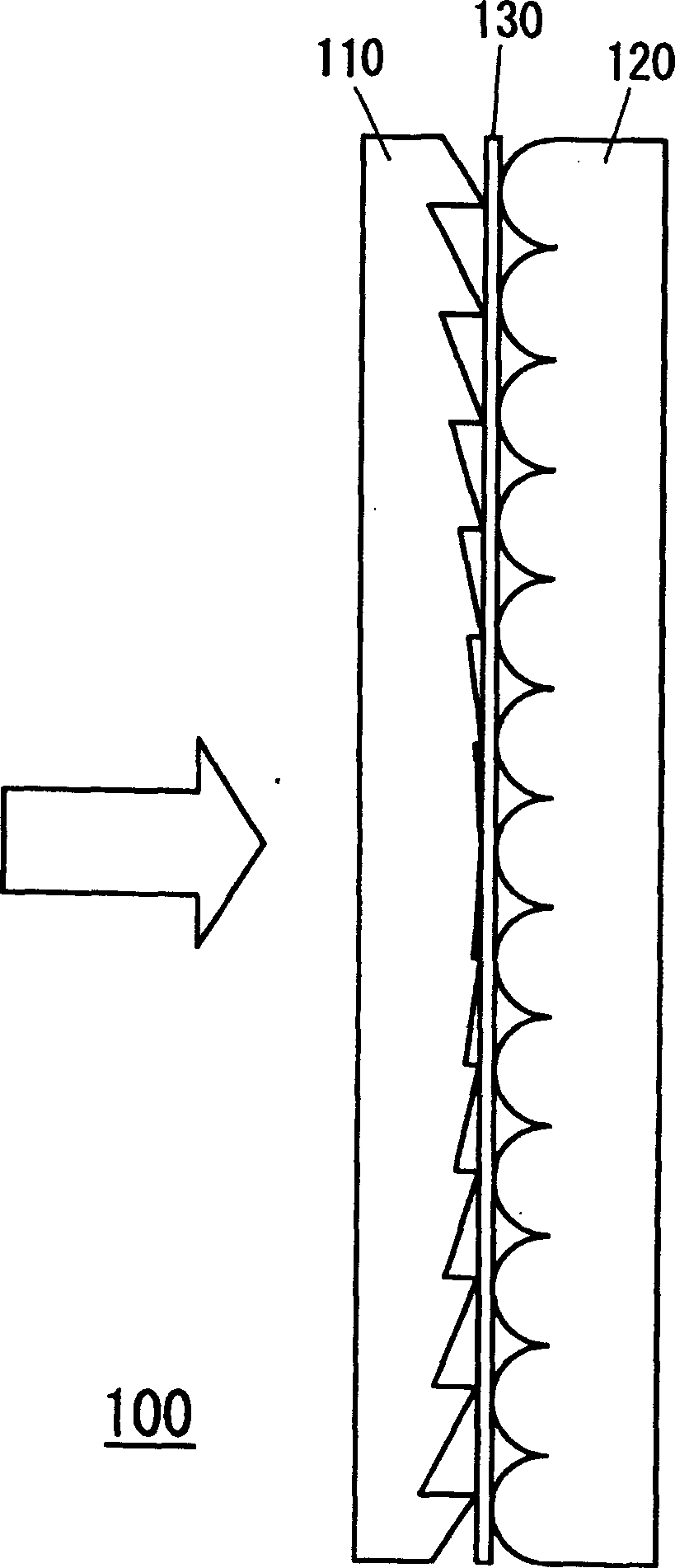
[0043] figure 1 The cross-sectional structure of the transmissive screen according to Embodiment 1 of the present invention is shown (the cross-sectional structure viewed from above). Such as figure 1 As shown, the transmissive screen 100 has a Fresnel lens part 110 with a Fresnel lens formed on the surface of the light exit surface, and is arranged on the exit surface side of the Fresnel lens part 110. A transmissive screen of the lens array portion 120 of a plurality of cylindrical lenses is formed on one side of the surface. In addition, the transmissive screen 100 also has a transparent flat plate 130 arranged between the Fresnel lens part 110 and the lens array part 120 .

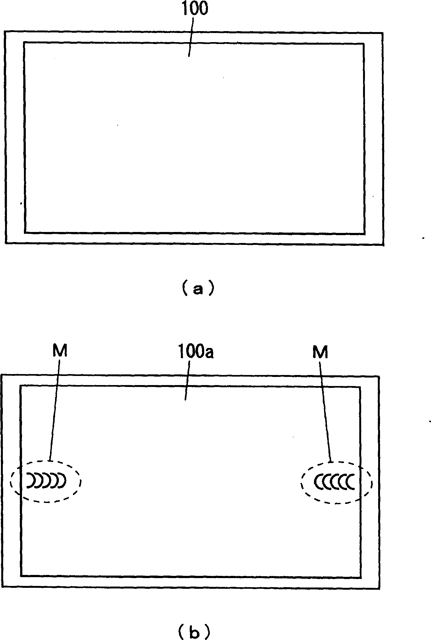
[0044] For this reason, since at least the peripheral portion of the transmissive screen 100 where the moiré fringes are conspicuously shown is provided with the tr...


PUM


Abstract

The invention seeks to provide a transmissive screen that can be manufactured at a low cost and show uniform diffusion and moire-free images over the entire screen, and to provide a rear projector provided with such a superior transmissive screen. A transmissive screen includes a Fresnel lens portion having Fresnel-lens components on its light-exiting face and a lens array facing the light-exiting face of the Fresnel lens portion and having many lenses on its light-incident face. The transmissive screen further includes separating means for separating the Fresnel lens portion from the lens array portion at least in the periphery of the screen. A rear projector includes such a superior transmissive screen.

Description

technical field [0001] The present invention relates to transmissive screens and rear projection projectors. Background technique [0002] In recent years, demand for rear projection projectors has been increasing as displays suitable for home theater monitors, large-screen TVs, and the like. [0003] Figure 7 The optical system of a rear projection projector is shown. The rear projection projector 10, such as Figure 7 As shown, there is a projection optical unit 20 for projecting an image, a light guide mirror 30 for guiding the projected image projected by the projection optical unit 20, and a projection image guided by the light guide mirror 30 for projecting. The transmissive screen 40 is arranged in the cabinet 50. [0004] As the transmissive screen 40 usable in such a rear projection projector 10, it is required that no moiré fringes occur on the screen surface. Japanese Unexamined Patent Publication No. 1-319025 discloses a transmissive screen configured so as n...

Claims


Application Information

Patent Timeline
Patent Type & Authority Applications(China)
IPC IPC(8): G03B21/56G02B3/08G02B5/04G03B21/10G03B21/62G03B21/625H04N5/74
CPCH04N9/3141G03B21/625G03B21/10G03B21/56
Inventor 唐泽穰儿坂口昌史
Owner SEIKO EPSON CORP
Why Eureka
Try Eureka