Ink cartridge

A technology for ink cartridges and inks, applied in printing and other directions, can solve problems such as troublesome mass production, increased number of operations, and increased cost of casting molds.

Inactive Publication Date: 2004-04-07
SAMSUNG ELECTRONICS CO LTD
View PDF1 Cites 2 Cited by
  • Summary
  • Abstract
  • Description
  • Claims
  • Application Information

AI Technical Summary

Problems solved by technology

[0006] However, with the conventional ink cartridge having the above-mentioned structure, the number of operations of the metal molding process of the ink cartridge 1 increases, and thus the cost of the molding process increases, causing trouble in mass production
In addition, when the long slit 5a is blocked, the air flows to the inkjet head chip through the tube 7, so that it cannot be printed normally.

Method used


Image

  • Ink cartridge
  • Ink cartridge
  • Ink cartridge

Examples


Embodiment Construction

[0017] The presently preferred embodiments of the invention will now be described in detail, examples of which are illustrated in the accompanying drawings, wherein like reference numerals refer to like elements throughout. The embodiments are described in order to explain the present invention by referring to the figures.

[0018] An ink cartridge according to an embodiment of the present invention will hereinafter be described in detail with reference to the accompanying drawings.

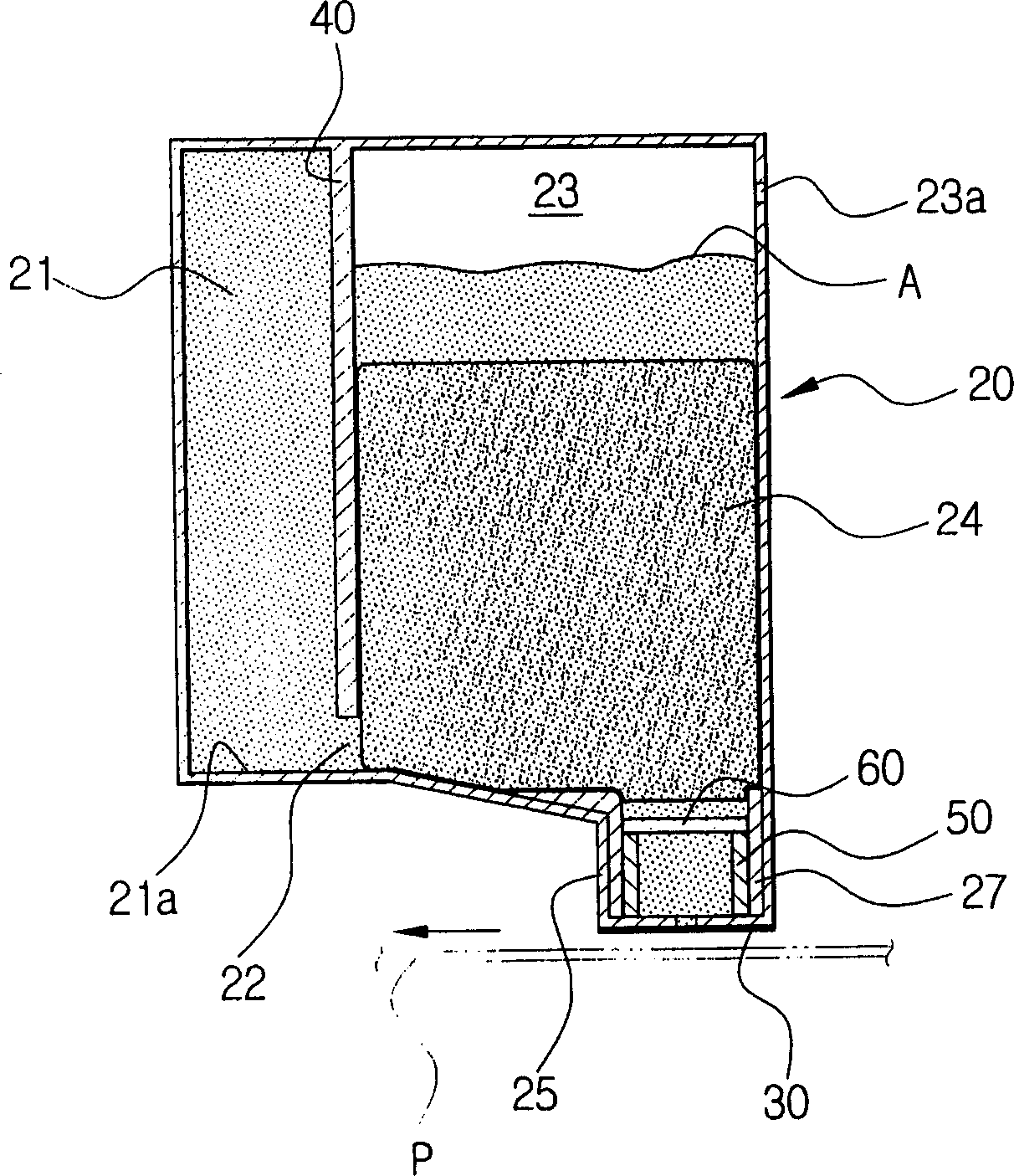
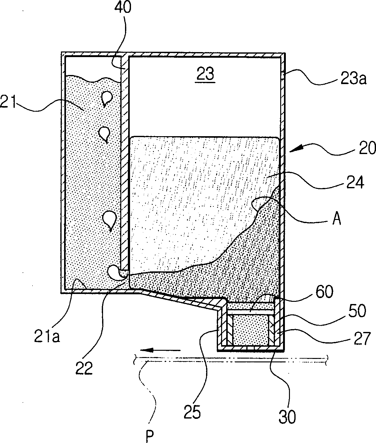
[0019] refer to figure 2 , the ink cartridge includes: the main body 20 which is divided into the ink chamber 21 and the foam chamber 23 inside, the inkjet head chip 30 arranged at the bottom of the foam chamber 23, the partition plate 40 which is arranged on the inside of the main body 20 and divides it into the ink chamber 21 and the foam chamber 23, The ink contained in the foam chamber 23 is supplied to the ink supply tube 50 of the inkjet head chip 30 , and the filter 60 provided at the up...


PUM


Abstract

An ink cartridge is provided with a main body divided into an ink chamber filled with ink and a foam chamber receiving an ink absorbent body, an ink head chip disposed at a lower portion of the foam chamber to spray the ink onto a printing paper, a partition forming a passage with a bottom of the main body to pass ink and air therethrough, and dividing an inside of the main body into the ink chamber and foam chamber, and an ink feeding pipe disposed lower than the passage and at a lower portion of the foam chamber to feed the ink in the foam chamber to the ink head chip.

Description

technical field [0001] The present invention relates to an ink cartridge, and more particularly, to an ink cartridge that prevents air from flowing into a print head chip during printing with ink. Background technique [0002] Generally, an ink cartridge of an inkjet printer includes a main body filled with ink, and ink in the main body is sprayed onto paper in a predetermined amount at a time by an ink head chip provided to the main body. [0003] figure 1 The ink cartridge 1 disclosed in US Pat. No. 5,742,311 is shown. refer to figure 1 , The ink cartridge 1 has a two-chamber structure for maintaining negative pressure. The inside of the ink cartridge 1 is divided into a foam chamber 4 containing foam (such as a sponge) 3, and an ink chamber 6 filled with ink 1. The ink chamber 6 and the foam chamber 4 are divided into left and right regions by a partition 5 . Between the lower end of the partition 5 and the inner bottom 1a of the ink cartridge 1, a channel 9 for pass...

Claims


Application Information

Patent Timeline
Patent Type & Authority Applications(China)
IPC IPC(8): B41J2/175
CPCB41J2/17513B41J2/175
Inventor 曹瑞铉郑明松李泳洙黄亨休
Owner SAMSUNG ELECTRONICS CO LTD
Why Eureka
Try Eureka