Shielded voltage-sharing circuit

A voltage equalizing circuit and shielded technology, applied in the field of shielded voltage equalizing circuits, can solve the problems of uneven voltage and reduced reliability of key components, so as to reduce the risk of damage, reduce voltage unevenness, and achieve balanced voltage distribution. Effect

Active Publication Date: 2018-10-26
GLOBAL ENERGY INTERCONNECTION RES INST CO LTD +1
View PDF4 Cites 2 Cited by
  • Summary
  • Abstract
  • Description
  • Claims
  • Application Information

AI Technical Summary

Problems solved by technology

[0007] In order to overcome the problem that the reliability of key components in the converter valve is reduced due to the inhomogeneity of the implementation scheme of electrical stress balance of the series thyristors and their components in the domestic and foreign converter valves, the present invention starts from the electrical principle of the voltage distribution of the series thyristors under the impact voltage Based on the shock voltage distribution mechanism of the converter valve, a shielded voltage equalizing circuit is provided. By electrically isolating the potential fixed point of the shield cover from the main circuit, only the end of the converter valve head is electrically connected to the shield cover, shielding the The leakage effect of the stray capacitance to the ground in the converter valve finally realizes the balanced distribution of the voltage of the large-scale serial thyristors in the wide frequency domain. 6.8kV / μs, which can realize the voltage distortion of the key components of the converter valve in the wide frequency domain, improve the reliability and insulation tolerance of the components, and have strong engineering application value

Method used


Image

  • Shielded voltage-sharing circuit
  • Shielded voltage-sharing circuit
  • Shielded voltage-sharing circuit

Examples


Embodiment Construction

[0039] The present invention will be described in further detail below in conjunction with the accompanying drawings.

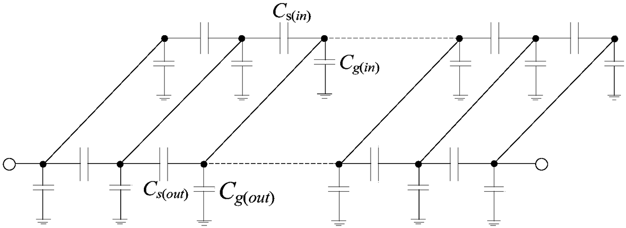
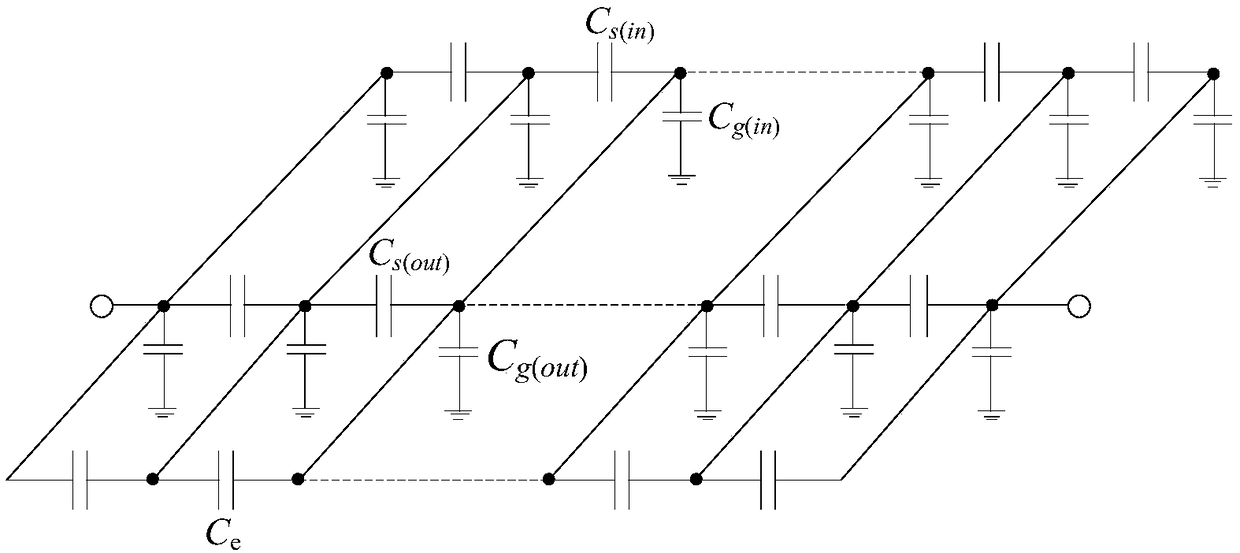
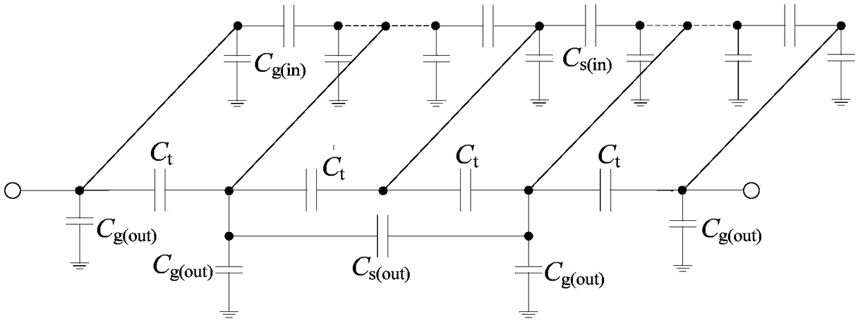
[0040] The zero-distortion, high-reliability shielded voltage equalizing circuit applied to converter valves provided by the embodiments of the present invention mainly adopts two technical solutions: converter valve impulse voltage analysis and capacitive shielded voltage equalization. The technical solutions are introduced as follows:

[0041] (1) Analysis of converter valve impulse voltage:

[0042] The thyristor in the converter valve adopts a chain-type series structure, and its structural size is comparable to the wavelength of the high-frequency impulse voltage. It cannot be regarded as a concentrated parameter circuit. It is necessary to use the transmission line theory to establish a distributed parameter model to analyze the wave process. When the converter valve is excited by high-frequency voltage, the saturated reactor as an inductance element h...


PUM


Abstract

The invention provides a shielded voltage-sharing circuit. The circuit includes a main circuit and an auxiliary circuit parallel to the main circuit; the main circuit includes a thyristor level equivalent circuit and a metal terminal to ground capacitance and saturation reactor equivalent circuits; and the auxiliary circuit includes M pi-type circuits which are in successive series. According to the technical schemes, shielding potential fixed point can be isolated from electric of the main circuit, the first end and the tail end of a converter valve and a shielding case are only in electricalconnection, and therefore, discharging effects in the converter valve on ground stray capacitance can be shielded, and voltage equalization distribution of wide frequency domain scaled series thyristors can be realized; and under the impact of steep waves, the unevenness of thyristor voltage is less than 1%, the largest voltage steepness can be reduced to 6.8 kV/[mu]s, no distortion of voltage ofkey components of the converter valve under wide frequency domain can be realized, the reliability and insulation tolerance of components can be enhanced, and the circuit has high engineering application values.

Description

technical field [0001] The invention relates to the technical field of UHV direct current transmission, in particular to a shielded voltage equalizing circuit. Background technique [0002] The converter valve is the core equipment to realize the AC-DC conversion of electric energy, and it is the "heart" of the DC project. It is very important whether it can operate reliably for a long time. There are many metal parts in the converter valve with different shapes and complex layout. There are a large number of stray capacitances between the metal parts and to the ground, and the frequency variation effect is significant. The thyristors and saturable reactors in the converter valve are strongly nonlinear. Under the action of 1200kV / μs steep wave impulse voltage, the stray capacitance of the shield will lead to uneven voltage distribution in the wide frequency range of hundreds of series thyristors and their components in the converter valve, and the unevenness will exceed 40%....

Claims


Application Information

Patent Timeline
Patent Type & Authority Applications(China)
IPC IPC(8): H02M1/00
CPCH02M1/00
Inventor 汤广福高冲贺之渊查鲲鹏周建辉盛财旺
Owner GLOBAL ENERGY INTERCONNECTION RES INST CO LTD
Why Eureka
Try Eureka