Flange type loose joint

A live joint and flange type technology is applied in the field of pipeline connection devices, which can solve the problems of taking into account difficulties and other problems, and achieve the effects of simple structure, small volume and flexible rotation.

Inactive Publication Date: 2004-04-14
上海晔光机电设备有限公司
View PDF0 Cites 3 Cited by
  • Summary
  • Abstract
  • Description
  • Claims
  • Application Information

AI Technical Summary

Problems solved by technology

[0003] The technical problem to be solved by the flange type union of the present invention is: when the existing pipe fitting connecting device satisfies the functions of good sealing and rotatability at the same time, it is difficult to balance both.

Method used


Image

  • Flange type loose joint
  • Flange type loose joint

Examples


Embodiment Construction

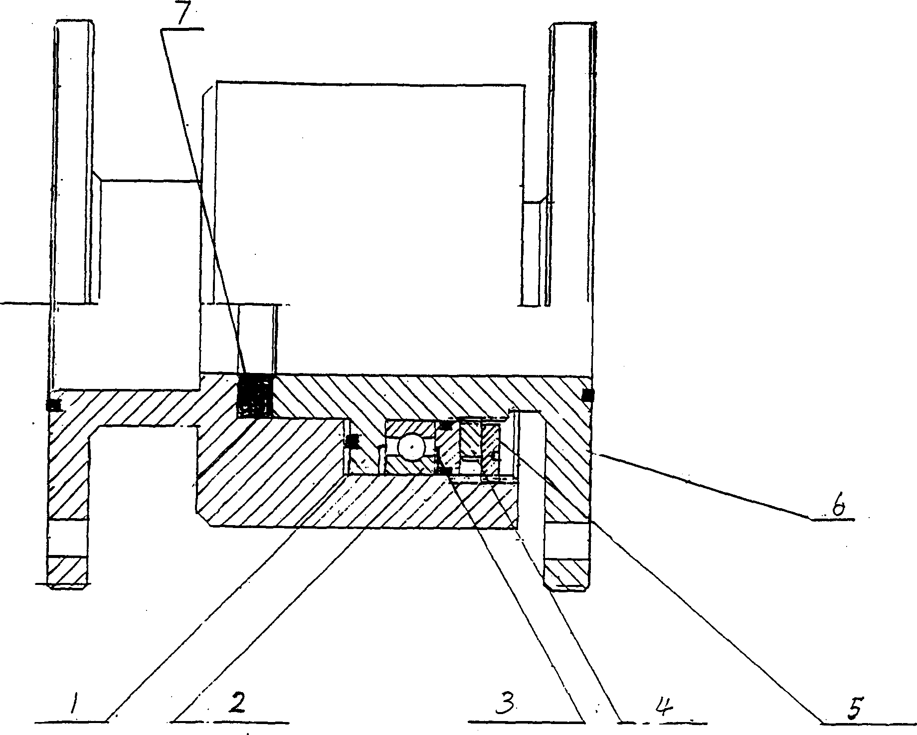
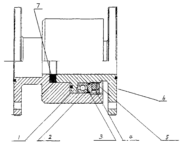
[0009] Such as figure 1 As shown, the flanged joint of the present invention is composed of a joint sleeve 1, a joint body 6, a rolling bearing 2, a retaining ring 3, an inner lock nut 4 and an outer lock nut 5. One end of the joint body 6 is disposed inside the joint sleeve 1, the retaining ring 3 is disposed on the joint body 6, and there is a shoulder on the joint body 6, and the rolling bearing 2 is disposed on the protrusion. Between the shoulder and the retaining ring 3, a seal 7 is provided at the contact between the inside of the joint sleeve 1 and the head of the joint body 6 and between the side of the shoulder and the joint sleeve 1. The inner and outer rings of the retaining ring 3 and the joint body 6 and the joint sleeve 1 are provided with seals to achieve sealing, the inner lock nut 4 is screwed on the joint body to compress the retaining ring 3, and the outer lock nut 5 is screwed into the joint sleeve 1 Compress the inner locking nut 4, and one end of the jo...


PUM


Abstract

The present invention relates to a flange union. It is characterized by that it adopts the rolling bearing as rotating component to make the union has flexible turnable function when said union is mounted and regulated. Said flange union is formed from union sleeve, union body, rolling bearing, retainer ring, internal block nut, external lock nut and sealing component. Said invention also provides its assembly method and concrete steps.

Description

technical field [0001] The invention relates to a pipeline connection device, in particular to a flanged joint. Background technique [0002] At present, in the field of pipelines, it is not difficult to solve the sealing problem of joints with existing coupling devices, but it is difficult to achieve both when the coupling pipe is required to have a rotatable function at the same time. Therefore, the existing connecting device cannot achieve both sealing and rotatability with a simple structure, which not only has poor flexibility, but also easily brings inconvenience to installation operation or use. Contents of the invention [0003] The technical problem to be solved by the flange type union of the present invention is: when the existing pipe fitting connecting device satisfies the functions of good sealing and rotatability at the same time, it is difficult to give consideration to both. Therefore, the existing connecting device cannot achieve both sealing and rotatab...

Claims


Application Information

Patent Timeline
Patent Type & Authority Applications(China)
IPC IPC(8): F16L23/02F16L27/08
Inventor 范文华金龙芳
Owner 上海晔光机电设备有限公司
Why Eureka
Try Eureka