Device and method for feeding fuel

a fuel and apparatus technology, applied in the direction of lighting and heating apparatus, combustion types, furnaces, etc., can solve the problems of difficult to readily control the mixing process and ratio, difficult to reach the flame zone near the heated subject, deterioration of combustion stability, etc., and achieve the effect of low oxygen density and high quality

Inactive Publication Date: 2006-09-12
NFK HLDG
View PDF4 Cites 111 Cited by
  • Summary
  • Abstract
  • Description
  • Claims
  • Application Information

AI Technical Summary

Benefits of technology

[0022]According to the arrangement of the present invention, the fuel is mixed with either or both of combustion gas extracted from a furnace and steam of steam supply means. The step of mixing the fuel with the combustion gas and / or steam, and the step of mixing the mixed fluid with combustion air are stepwisely carried out, and therefore, flexibility and reliability of mixing control of fuel, combustion air and combustion gas and / or steam are significantly improved. A large quantity of mixed fluid containing a thin fuel component is produced in the mixing area of the fuel and combustion gas and / or steam. The mixed fluid is fed to the combustion area, as being a large quantity of fuel gas flow having a momentum controllable independently of in-furnace combustion gas circulation flow. Accordingly, the fuel gas flow introduced into the furnace can mix with the combustion air flow without being substantially subject to influence of in-furnace combustion gas circulation flow. Thus, mixing process and mixing ratio of fuel and combustion gas can be variably controlled, independently of control of in-furnace combustion gas re-circulation flow.
[0024]According to such an arrangement, a large quantity of fuel gas flow with an independently controllable momentum is introduced into the combustion area, so that the characteristics of flame produced in the combustion area can be controlled by control of fuel gas flow introduced into the combustion area as well as control of combustion air flow. Further, the fuel is preliminarily mixed with the combustion gas and / or steam, and thereafter, mixed with the combustion air, so that flexibility and reliability of mixing control of fuel and combustion air is significantly improved, in comparison with a conventional combustion method in which air and / or fuel is mixed with in-furnace circulation flow in the furnace.
[0026]According to this invention, characteristics of flame produced in the combustion area can be controlled by controlling a relatively large quantity of fuel gas containing a thin fuel, whereby an exothermic combustion reaction in the combustion area can be adjusted, and radiation and convection heat transfer effects of flame acting on the heated subject can be improved.
[0028]If desired, a part of combustion gas and / or steam may be mixed with combustion air. The combustion air, which is diluted with the combustion gas and / or steam to have a low oxygen density, is introduced into the combustion area to be mixed with the high-temperature fuel gas of a low oxygen density as set forth above. The fuel component contained in the fuel gas more slowly takes a combustion reaction with the combustion air of a low oxygen density so as to produce a low-temperature flame in a wide area with a local heat of flame being restricted.
[0029]Further, steam contained in the combustion gas, high-temperature steam heated by mixing or heat exchange with the high-temperature combustion gas, or high temperature steam heated up to a temperature equal to or higher than 700 deg. C. by independent steam heating means, causes a thermal decomposing reaction and / or a steam reforming reaction of fuel hydrocarbon, and therefore, the fuel hydrocarbon is reformed to a high quality reformed gas containing a relatively large quantity of hydrocarbon radical, hydrogen, carbon, carbon monoxide and so forth. Thus, it is possible to reform a relatively heavy gravity or low (or degraded) quality hydrocabonaceous fuel, such as heavy oil, to a light gravity or high (or good) quality hydrocabonaceous fuel, before the fuel is mixed with the combustion air.

Problems solved by technology

Therefore, it is difficult to readily control the mixing process and ratio.
Especially, as regards a combustion furnace which relatively often varies in heat load and furnace temperature in correspondence with its operating condition, mixing of combustion gas re-circulation flow with air and / or fuel might result in deterioration of combustion stability when the temperature of combustion air is lowered, and therefore, any countermeasure for overcoming this drawback is required.
For example, since fuel and air taking a combustion reaction in a mixing area almost entirely burn near a burner, a flame is merely formed near the burner, and therefore, it is difficult for the flame to reach a zone near a heated subject.
However, the flow rate of fuel fluid is greatly smaller than that of air flow, and therefore, owing to a power of a large amount of air, the power of fuel fluid flow is de-energized to lose its power immediately after its injection.
Thus, it is difficult to increase a distance of travel of the fuel fluid.
However, it is difficult in practice to surely control the mixing of these fluids in dependence on a conventional combustion skill in which an in-furnace circulation flow of combustion gas is mixed with a fuel or air flow within an in-furnace area of the furnace.

Method used


Image

  • Device and method for feeding fuel
  • Device and method for feeding fuel
  • Device and method for feeding fuel

Examples


Embodiment Construction

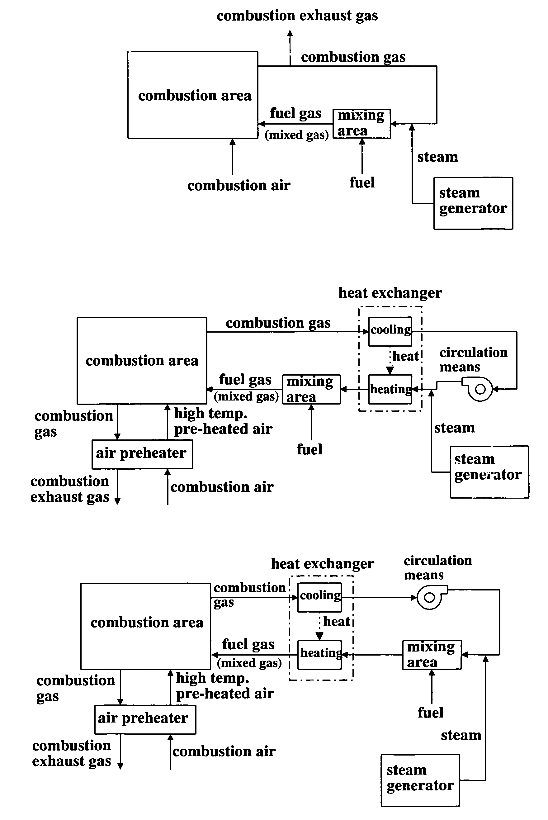
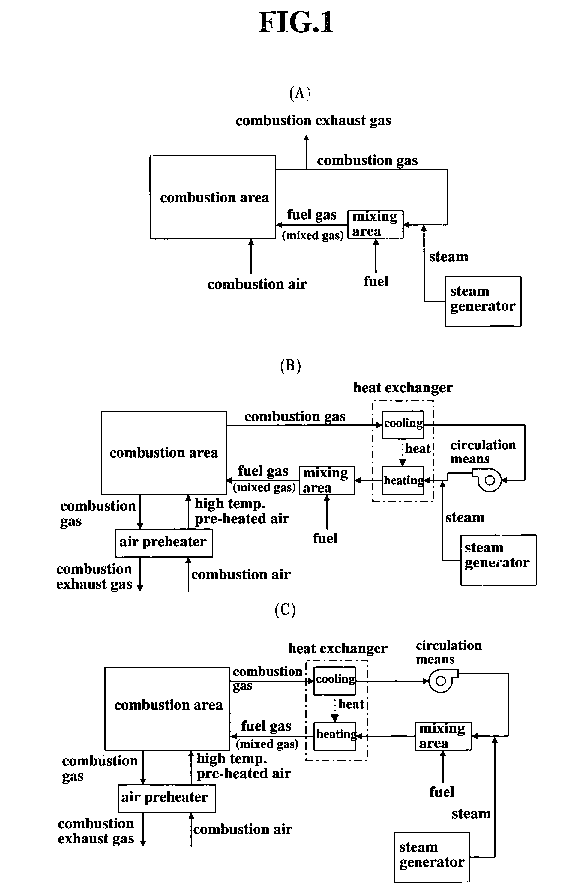
[0046]A fuel feeding device as shown in FIG. 1 (A) comprises a combustion gas extraction passage for extracting a combustion gas from a combustion area, a mixing area for a fuel and the combustion gas, and a fuel supply passage for feeding the fuel to the mixing area. The high-temperature combustion gas produced in the combustion area is extracted therefrom through the combustion gas extraction passage. A predetermined flow rate of combustion gas is exhausted out of the system as a combustion exhaust gas, and the reminder thereof is introduced into the mixing area. If desired, steam of a steam generator is injected into the combustion gas so as to adjust the content of steam in the combustion gas. A hydrocarbonaceous fuel is introduced into the mixing area through the fuel supply passage to be mixed with the combustion gas, so that a high temperature mixed gas (a fuel gas) comprising the fuel diluted with the combustion gas is produced in the mixing area.

[0047]In general, the combus...


PUM


Abstract

The present invention provides a fuel feeding apparatus and method for improving the controllability of mixing process and mixing ratio of fuel and combustion air, and a combustion system and method for effecting new combustion properties. The fuel feeding apparatus of the combustion system has fuel feeding means, combustion gas extraction means, steam supply means, mixing means and fuel gas introduction means. The combustion gas extraction means extracts combustion gas of a combustion area therefrom. The mixing means mixes the fuel of fuel feeding means with at least one of combustion gas extracted from the furnace and steam of a steam generator. The fuel gas introduction means introduces a mixed fluid of combustion gas, steam and fuel to the combustion area as a fuel gas, and allows the fuel gas to be mixed with the combustion air. A step of mixing the fuel with the combustion gas after extracted from the furnace and a step of mixing the fuel gas with the combustion air are stepwisely carried out, so that the controllability of mixing process and ratio of the air and fuel is improved. Such a control of fuel gas flow enables control of characteristics of flame and production of flame with new properties in the combustion area.

Description

TECHNICAL FIELD OF THE INVENTION[0001]The present invention relates to apparatus and method for feeding fuel, and more particularly, to such apparatus and method for improving controllability of mixing of fuel and combustion air, characteristics of combustion of fuel, and further, properties of flame in a combustion area, and so forth.BACKGROUND OF THE INVENTION[0002]An industrial furnace, such as a tubular furnace, metal heating furnace, ceramic industrial kiln, metal melting furnace, gasification melting furnace, boiler or a combustion heating type of heating apparatus, such as a radiant tube burner, is provided with fuel feeding means for feeding hydrocarbonaceous fuel, air supply means for supplying combustion air, and a combustion means for mixing the fuel and combustion air to burn the fuel, such as a burner. The fuel and combustion air mixed in the combustion means produce flame in a combustion area by diffusion combustion. In this kind of combustion means, the actual amount ...

Claims


Application Information

Patent Timeline
Patent Type & Authority Patents(United States)
IPC IPC(8): F27D13/00F23C9/00F23D14/66F23L7/00F23L15/02F23L15/04
CPCF23C9/00F23L15/04F23L7/005F23L15/02F23D14/66F23C2202/10F23C2202/20F23C2202/30F23K2401/10F23K2900/01041F23K2400/10Y02E20/34F23C1/00
Inventor HASEGAWA, TOSHIAKIMOCHIDA, SUSUMUHOSHINO, LEGAL REPRESENTATIVE, KIYOKOHOSHINO, DECEASED, TOSHIHUMI
Owner NFK HLDG
Why Eureka
Try Eureka