Method for mounting ship stern shaft

An installation method and stern shaft technology, applied in the direction of mechanical gear transmission, etc., to achieve the effect of reducing labor intensity

Active Publication Date: 2004-04-21
HUDONG ZHONGHUA SHIPBUILDINGGROUP
View PDF0 Cites 31 Cited by
  • Summary
  • Abstract
  • Description
  • Claims
  • Application Information

AI Technical Summary

Problems solved by technology

[0003] The technical problem to be solved by the present invention is to overcome the above-mentioned difficulties in the installation of the ship stern shaft in the prior art, provide a method for installing the ship stern

Method used


Image

  • Method for mounting ship stern shaft
  • Method for mounting ship stern shaft
  • Method for mounting ship stern shaft

Examples


Embodiment Construction

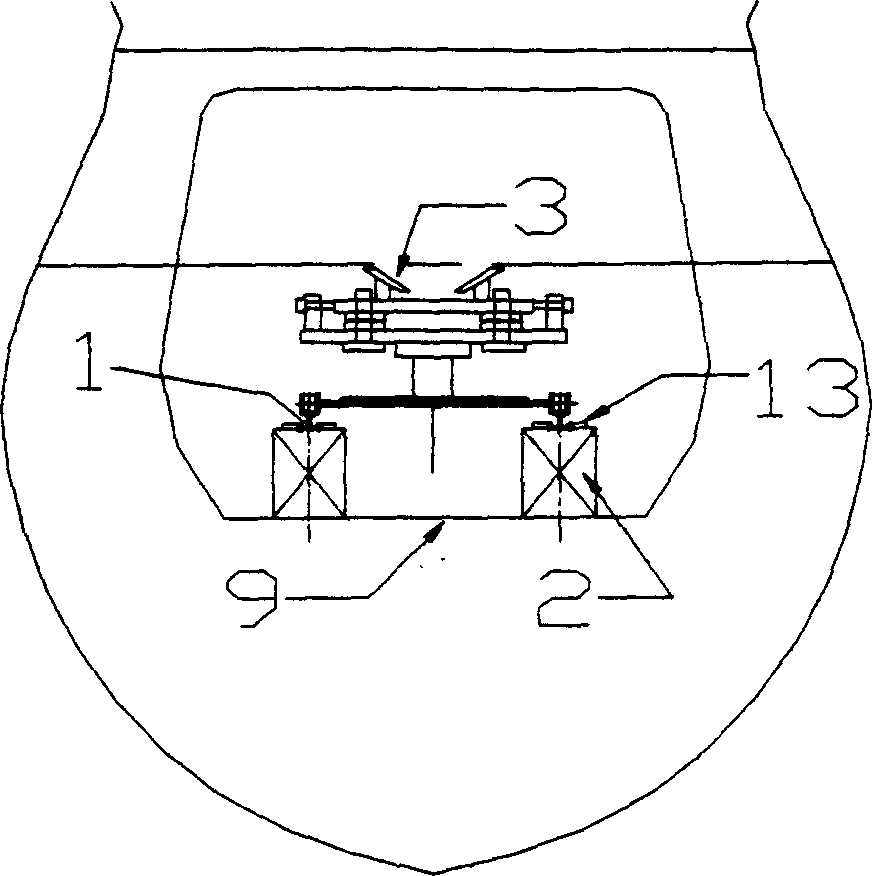
[0035] See first figure 1 and figure 2 , the ship stern shaft installation method of the present invention comprises the following specific steps:

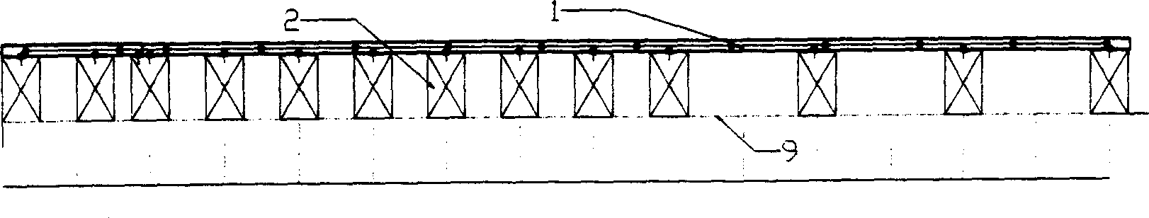
[0036] ①. Place a dunnage box 2 on the inner bottom plate 9 of the cabin, and lay a track 1 facing the stern shaft tube 6 on the dunnage box 2, and press it with the track pressure plate 13 of the stern shaft installation trolley;

[0037] ②. Place two stern shaft installation trolleys 3 and 3’ on track 1, and use the trolley height adjustment bolt 12 to preliminarily adjust the height of the stern shaft installation trolley;

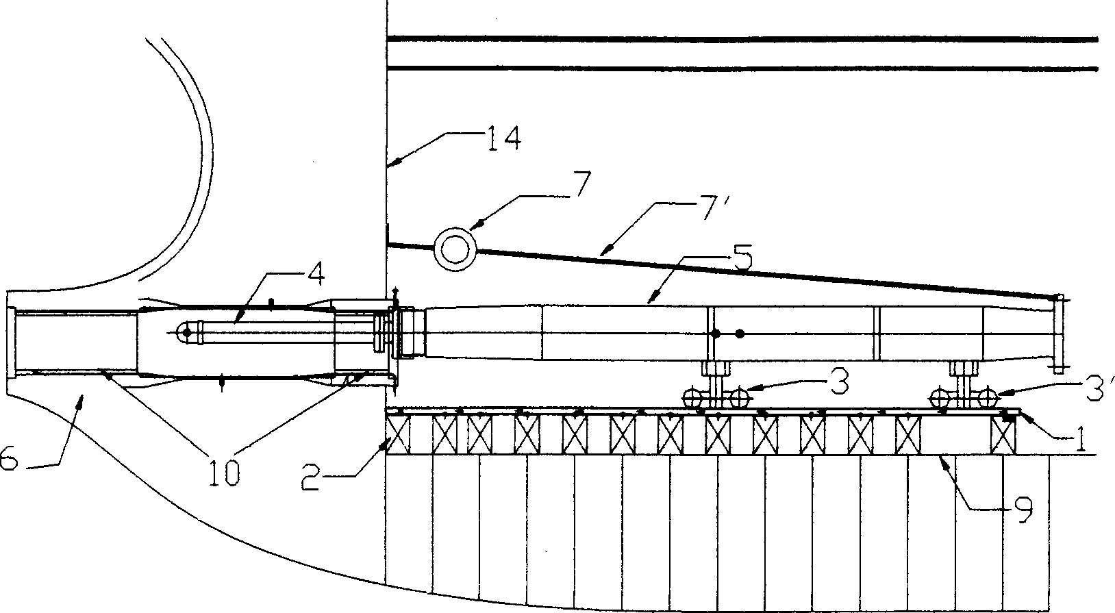
[0038] ③. Hoist the stern shaft extension rod 4 to the front of the compartment (see image 3 , 4 ), then hoist the stern shaft 5 into and place it on the concave brackets of the two stern shaft installation trolleys 3, 3', and then install the stern shaft connecting rod 4 to the rear end of the stern shaft 5;

[0039] ④.Clean the extension rod 4 and the stern shaft 5, and carefully fine-tune the two s...


PUM


Abstract

A method for installing the propeller shaft of ship features that an installing carrier, a radially regulating pulley hoist and axially tracting pulley hoist are combined for transporting and regulating the propeller shaft, several underlaying cases are designed according to the height of the central line of said propeller shaft, a track for said installing carrier is laid, and an elongating rod is additionally attached to the tail end of said propeller shaft.

Description

Technical field: [0001] The invention relates to ship manufacturing and installation, in particular to a method for installing a ship stern shaft with a relatively large size. Background technique: [0002] At present, the installation of the ship stern shaft is to pull the stern shaft axially and radially with a chain hoist, and then slowly insert the stern shaft into the stern tube. Although the installation is simple, the degree of mechanization is too low. When the shaft passes through the stern tube, it is not easy to align, and collisions often occur, often causing accidents where the stern tube bushing is damaged. The installation work is not safe enough, the installation period is correspondingly prolonged, and the labor intensity of the installation workers is also relatively high. Invention content: [0003] The technical problem to be solved by the present invention is to overcome the above-mentioned difficulties in the installation of the ship stern shaft in th...

Claims


Application Information

Patent Timeline
IPC IPC(8): B63H23/04
Inventor 黄卫丰
Owner HUDONG ZHONGHUA SHIPBUILDINGGROUP
Why Eureka
Try Eureka