Chucking

A technology of fixtures and receiving parts, which is applied in the direction of electric circuits or fluid pipelines, vehicle parts, transportation and packaging, etc. It can solve the problems of operability deterioration, achieve good operability, reduce the installation area, and be easy to elastically deform.

Inactive Publication Date: 2004-04-21
NIFCO INC +1
View PDF1 Cites 5 Cited by
  • Summary
  • Abstract
  • Description
  • Claims
  • Application Information

AI Technical Summary

Problems solved by technology

[0011] However, in order to hold the pipes 102, 104 on the upper and lower clamp parts 124 respectively in the state where the engaging portion 100 is engaged with the stud bolts protruding from the vehicle body panel, the insertion direction of the pipes 102, 104 becomes two up and down. direction, thereby deteriorating operability

Method used


Image

  • Chucking
  • Chucking
  • Chucking

Examples


Embodiment Construction

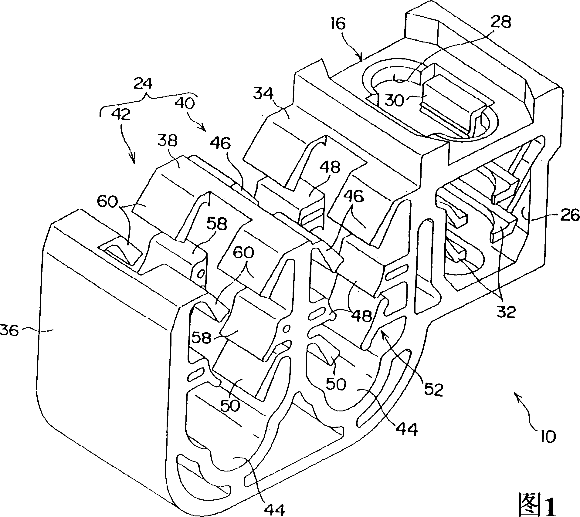
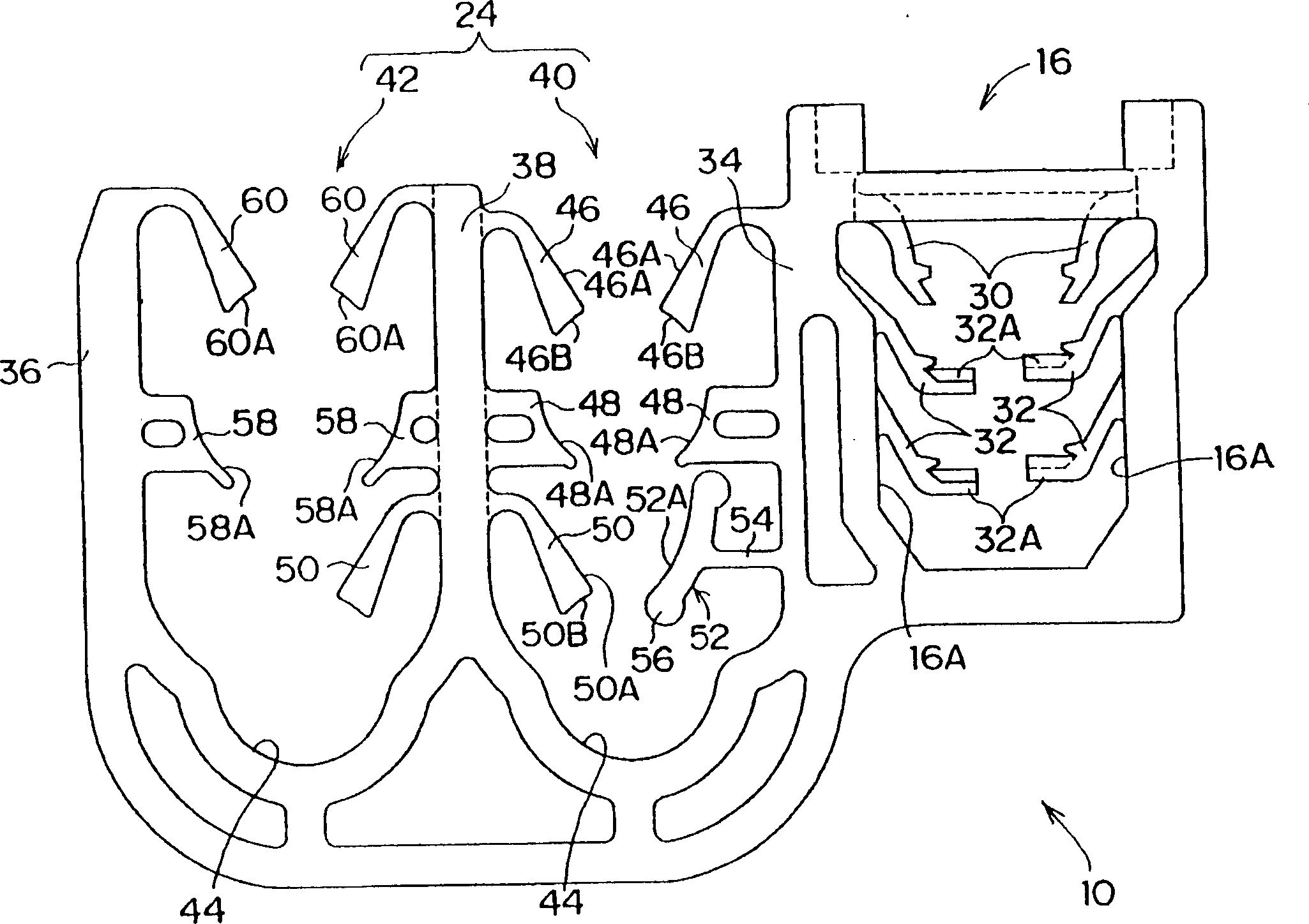
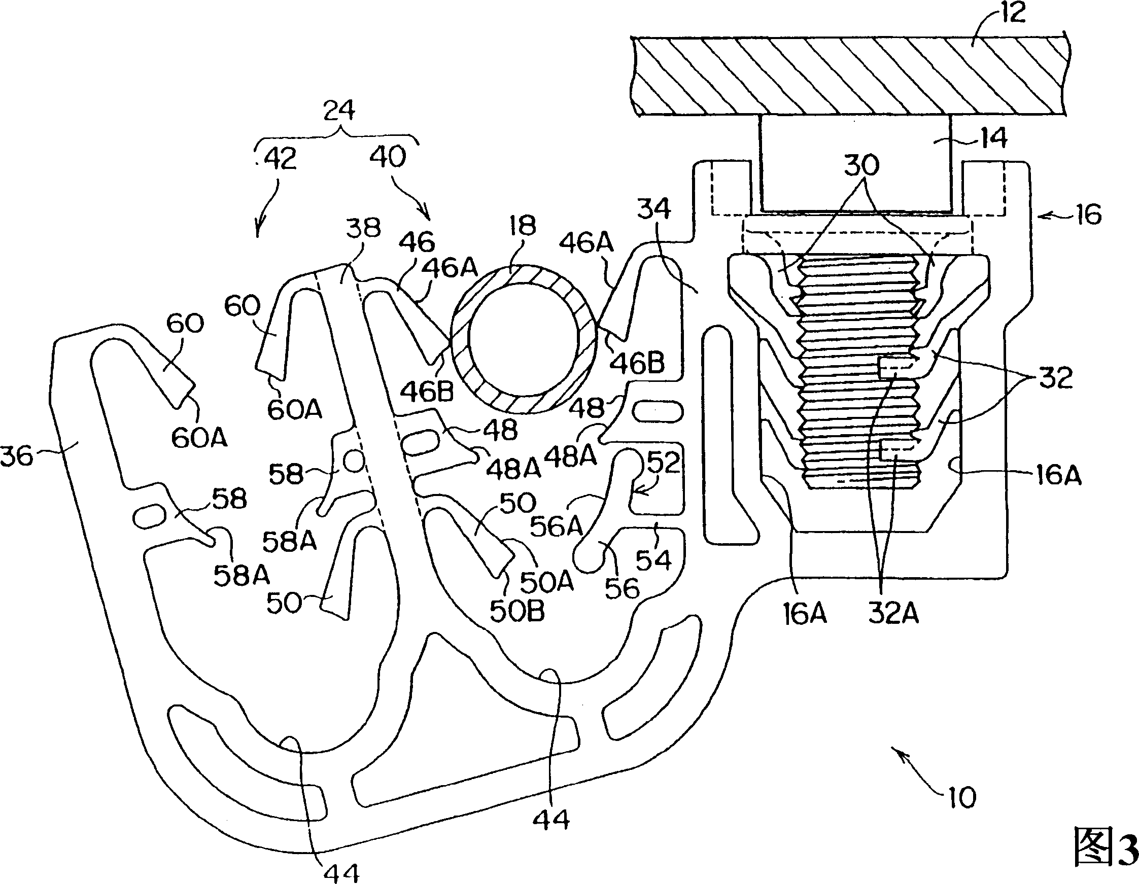
[0030] 1 to 5 show a jig 10 according to this embodiment. The clamp 10 is composed of an engaging portion 16 engaged with a stud bolt 14 protruding from a vehicle body panel 12 , and a clamp portion 24 holding rod-shaped air-conditioning pipes 18 , 20 , 22 .

[0031] The engagement portion 16 is formed in a box shape, has an opening 26 on the side wall, and a hole 28 into which the stud bolt 14 protruding from the vehicle body panel 12 is formed on the upper surface. A pair of guide pieces 30 protrude downward and inwardly from the hole portion 28 , and guide the inserted stud bolts 14 to the pair of detachment prevention pieces 32 .

[0032] The anti-off piece 32 protrudes from two places above and below the inner side wall 16A of the engaging portion 16, and its front end 32A is horizontal. The distance between the upper and lower sides of the anti-off piece 32 matches the pitch of the thread of the stud bolt 14, and the front end 32A of the anti-off piece 32 engages with t...


PUM


Abstract

When inserting pipes 18 and 20 into a holding part 40, the pipes are inserted from the same inserting port. Thus, the inserting direction of the pipes 18 and 20 into the holding part 40 becomes the same. Thus, the workability is improved, and work manhours can be reduced. Since the pipe 20 is regulated on the movement by a holding piece 56 of a stopper 52 before the pipe 20 falls downward by passing between a receiving part 48 by vibration of a vehicle by arranging one end part of the holding piece 56 of the stopper 52 under the pipe 20 in a state of installing the pipes 18 and 20 in the holding part 40 by fixing a clamp 10 to a body panel 12, the passing of the pipe 20 to between a receiving part 44 is checked. Thus, the pipe 20 does not fall to the inner side of the holding part 40.

Description

technical field [0001] The present invention relates to a jig for attaching a pipe or the like for an automobile air conditioner to an attachment object such as a body panel. Background technique [0002] Air-conditioning pipes and the like are attached to predetermined positions on the body panels of automobiles through jigs. Fixtures such as Figure 6 As shown (Patent Document 1), it includes: an engaging portion 100 that engages with a stud bolt protruding from a vehicle body panel; and a clamp portion 106 that holds pipes 102 , 104 . [0003] Arc-shaped holders 108 , 110 matching the outer diameters of the pipes 102 , 104 are formed on the jig portion 106 . Supporting walls 112, 114 are respectively provided on the holding tables 108, 110, and elastically deformable guide pieces 116, 118 extending toward the center of the holding tables 108, 110 extend from the front ends of the supporting walls 112, 114. [0004] Furthermore, opposite the support walls 112 , 114 , gui...

Claims


Application Information

Patent Timeline
Patent Type & Authority Applications(China)
IPC IPC(8): F16L3/12F16L3/22F16L3/223
CPCF16L3/1203B60R16/0215F16L3/223
Inventor 河上泰章三浦秀哉
Owner NIFCO INC
Why Eureka
Try Eureka