Laser machining apparatus and laser machining method

a laser machining and laser machining technology, applied in the direction of soldering apparatus, manufacturing tools,auxillary welding devices, etc., can solve the problems of inability to achieve the effect of improving work efficiency, no large installation area, and reducing machining efficiency

Active Publication Date: 2005-03-03
HITACHI SEIKO LTD
View PDF14 Cites 15 Cited by
  • Summary
  • Abstract
  • Description
  • Claims
  • Application Information

AI Technical Summary

Benefits of technology

[0007] It is an object of the invention to solve the aforementioned problems by providing a laser machining appa

Problems solved by technology

However, in case of the laser machining apparatus comprising a plurality of work mounting sections, it takes time to transfer workpieces and the machining efficiency drops if the workpieces are to be transferred one by one.
Still more, although the transfer time may be shortened by provi

Method used


Image

  • Laser machining apparatus and laser machining method
  • Laser machining apparatus and laser machining method
  • Laser machining apparatus and laser machining method

Examples


first embodiment

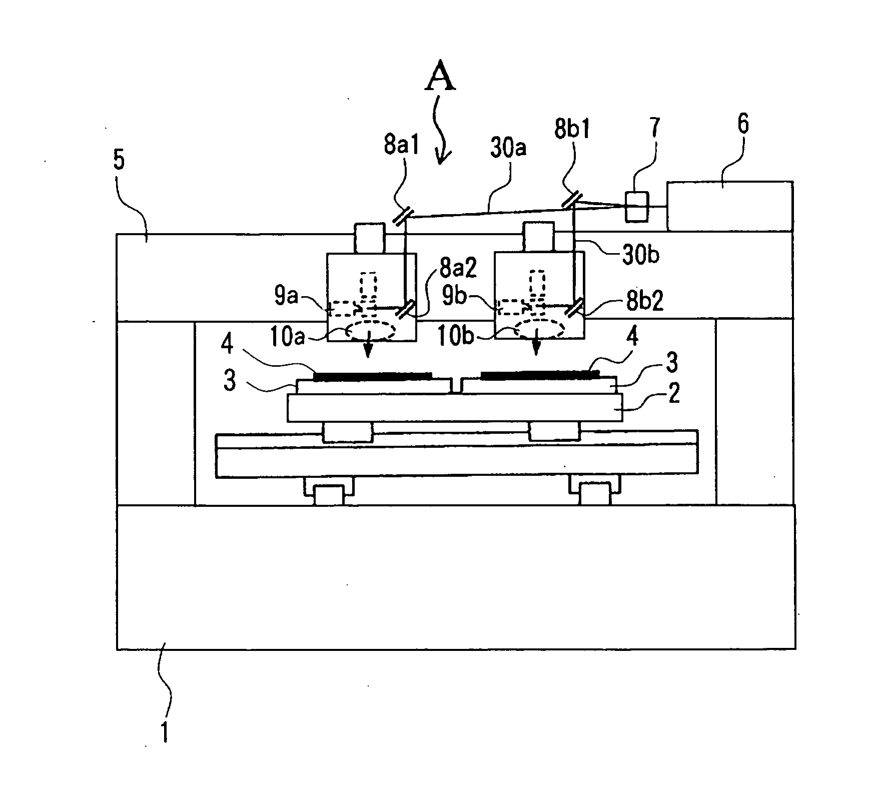
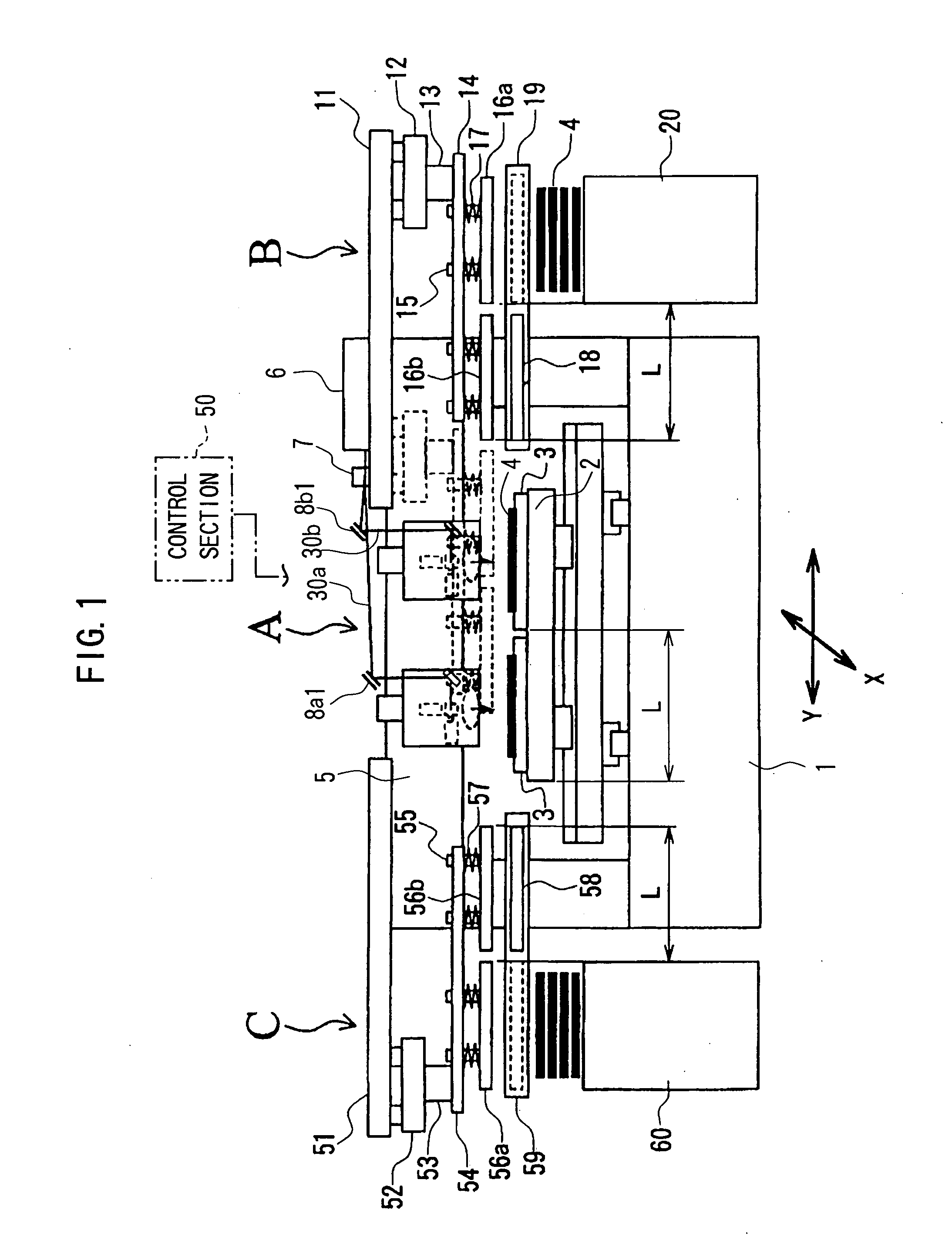
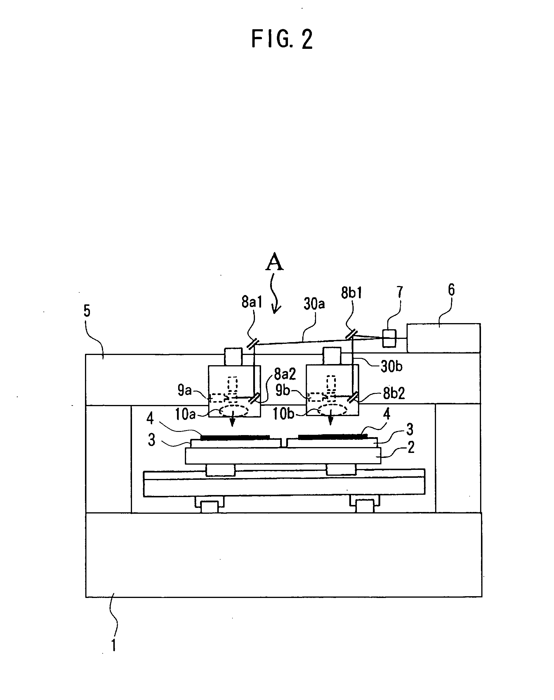
[0032]FIG. 1 is a front view showing the whole of a laser machining apparatus according to a first embodiment of the invention and FIG. 2 is a front view showing a body of the laser machining apparatus. As shown in FIG. 1, the inventive laser machining apparatus is composed of a body portion A thereof, a carrying-in unit B and a carrying-out unit C.

[0033] The structure of the body portion A will be explained at first with reference to FIGS. 1 and 2. An XY table 2 is disposed on a bed 1 of the body portion A. The XY table 2 is movable on the bed 1 horizontally in the X and Y directions. A plurality of (two in the figure) tables (work mounting sections) 3 is fixed on the XY table 2 separately by a distance L in the Y-axis direction. A plurality of holes connected to a hollow section inside is formed on the surface of the table 3. The hollow sections are connected to a vacuum source not shown so that the table 3 can adsorb / release the workpiece 4.

[0034] A gate-type column 5 is fixed ...

second embodiment

[0073] By the way, there is a case when workpieces are stacked by interleaving a soft sheet, e.g., a sheet of paper, resin or the like (hereinafter referred to as an ‘interleaf’) between the workpieces in order to prevent scratch of the surface of the workpiece. A laser machining apparatus suitable for such a case will be explained below. FIG. 3 is a front view showing the whole structure of the laser machining apparatus according to a second embodiment of the invention, wherein he same reference characters denote the same or corresponding parts with those in FIGS. 1 and 2 and an explanation thereof will be omitted here.

[0074] In FIG. 3, a rail 62 is disposed at the position in the vertical direction between the rail 19 and the supplying stocker 20. An interleaf receiving table (interleaf mounting table) 61 is disposed on the rail 62 so as to be movable horizontally in the Y-direction. Similarly to the work receiving table 18, the standby position of the interleaf receiving table 6...

third embodiment

[0119]FIG. 4 is a plan view showing a structure of a laser machining apparatus according to a third embodiment of the invention and FIG. 5 is a view in the direction of an arrow K in FIG. 4, wherein the same or corresponding parts with those in FIGS. 1 and 2 will be denoted by the same reference numerals and an explanation thereof will be omitted here. It is noted that a front view of the apparatus of the present embodiment is substantially the same with that shown in FIG. 1.

[0120] An interleaf carrying-out unit (interleaf removing and carrying-out unit) D is disposed behind the carrying-in unit (supply-side transfer unit) B in FIG. 1 and an interleaf carrying-in unit (interleaving unit) E is disposed behind the carrying-out unit (discharge-side transfer unit) C in FIG. 1, respectively (see FIG. 4). Here, the interleaf carrying-out unit D is a unit for retaining an interleaf 4s on a workpiece 4 placed on the supplying stocker 20 and for placing it on an interleaf discharging table ...


PUM


Abstract

There is provided a laser machining apparatus, and a laser machining method using the same, which allows an installation area thereof to be reduced while improving working efficiency. The laser machining apparatus has a body portion having a plurality of laser irradiating sections and work mounting sections, a supplying stocker for supplying workpieces, and a discharging stocker for discharging the workpieces. The apparatus further comprises a supply-side transfer unit having work retaining tables capable of attaching/detaching the workpieces and of the same number with the laser irradiating sections, and moving the work retaining tables in the vertical and horizontal directions, and a discharge-side transfer unit having work retaining tables capable attaching/detaching the workpieces and of the same number with the laser irradiating sections, and moving the work retaining tables in the vertical and horizontal directions. The supply-side unit causes the plurality of supply-side work retaining tables to adsorb the workpieces from the supplying stocker one after another and moves these supply-side work retaining tables to the work mounting sections to place the workpieces thereon. The discharge-side unit causes the discharge-side work retaining tables to adsorb the workpieces which have been machined at the work mounting sections to move and discharge those workpieces to the discharging stocker.

Description

BACKGROUND OF THE INVENTION [0001] 1. Field of the Invention [0002] The present invention relates to a laser machining apparatus comprising a plurality of laser irradiating sections and work mounting tables disposed so as to face to the laser irradiating sections and to a laser machining method using the laser machining apparatus. [0003] 2. Description of Related Art [0004] As a prior art laser machining apparatus, there has been known a laser machining apparatus having a plate-like work supplying unit, as disclosed in Japanese Patent Laid-open No. 2001-139170 for example, comprising work transferring means for transferring plate-like workpieces from a first work mounting section to a second work mounting section, workpiece thickness detecting means for detecting whether or not one workpiece is mounted on the second work mounting section, and work transfer control means for controlling, when the workpiece thickness detecting means detects that a plurality of workpieces is mounted on...

Claims


Application Information

Patent Timeline
IPC IPC(8): B23K37/047B23K26/10B65H3/08B65H29/32
CPCB23K26/0838B23K37/047B65H3/0816B65H29/32B65H2406/342B65H2406/351Y10T29/5124B65H2701/1928B65H2701/18264B65H2220/09B23K26/10
Inventor ITO, YASUSHINARUSE, FUTAOMARUYAMA, OSAMU
Owner HITACHI SEIKO LTD
Why Eureka
Try Eureka