Vacuum processing apparatus and operating method of vacuum processing apparatus

a vacuum processing and vacuum technology, applied in the direction of electrical apparatus, conveyor parts, electric discharge tubes, etc., can solve the problems of long time for work and stopping the processing of samples by the vacuum processing apparatus, damage to the availability of the entire vacuum processing apparatus, etc., to improve the efficiency of maintenance work and improve processing efficiency.

Active Publication Date: 2019-05-23
HITACHI HIGH-TECH CORP
View PDF2 Cites 3 Cited by
  • Summary
  • Abstract
  • Description
  • Claims
  • Application Information

AI Technical Summary

Benefits of technology

[0022]According to the invention, it is possible to provide a vacuum processing apparatus

Problems solved by technology

In the above-described related art, problems have arisen because consideration on the following points was insufficient.
Therefore, when performing maintenance or inspection work, such as wet cleaning, with respect to one processing unit, a space for the worker to access the inside of the target vacuum container or to perform the work with respect to the inside of the processing chamber is reduced, there is only the space for the worker to perform work only in one direction with respect to one vacuum container or for one worker to perform the work, the time for the work and the time fo

Method used


Image

  • Vacuum processing apparatus and operating method of vacuum processing apparatus
  • Vacuum processing apparatus and operating method of vacuum processing apparatus
  • Vacuum processing apparatus and operating method of vacuum processing apparatus

Examples


embodiments

[0050]Hereinafter, embodiments of the invention will be described with reference to FIGS. 1 to 26. In addition, in the drawings, the same reference numerals indicate the same configuration elements, and the description of the configuration elements to which the same reference numerals are given in a plurality of drawings will be omitted.

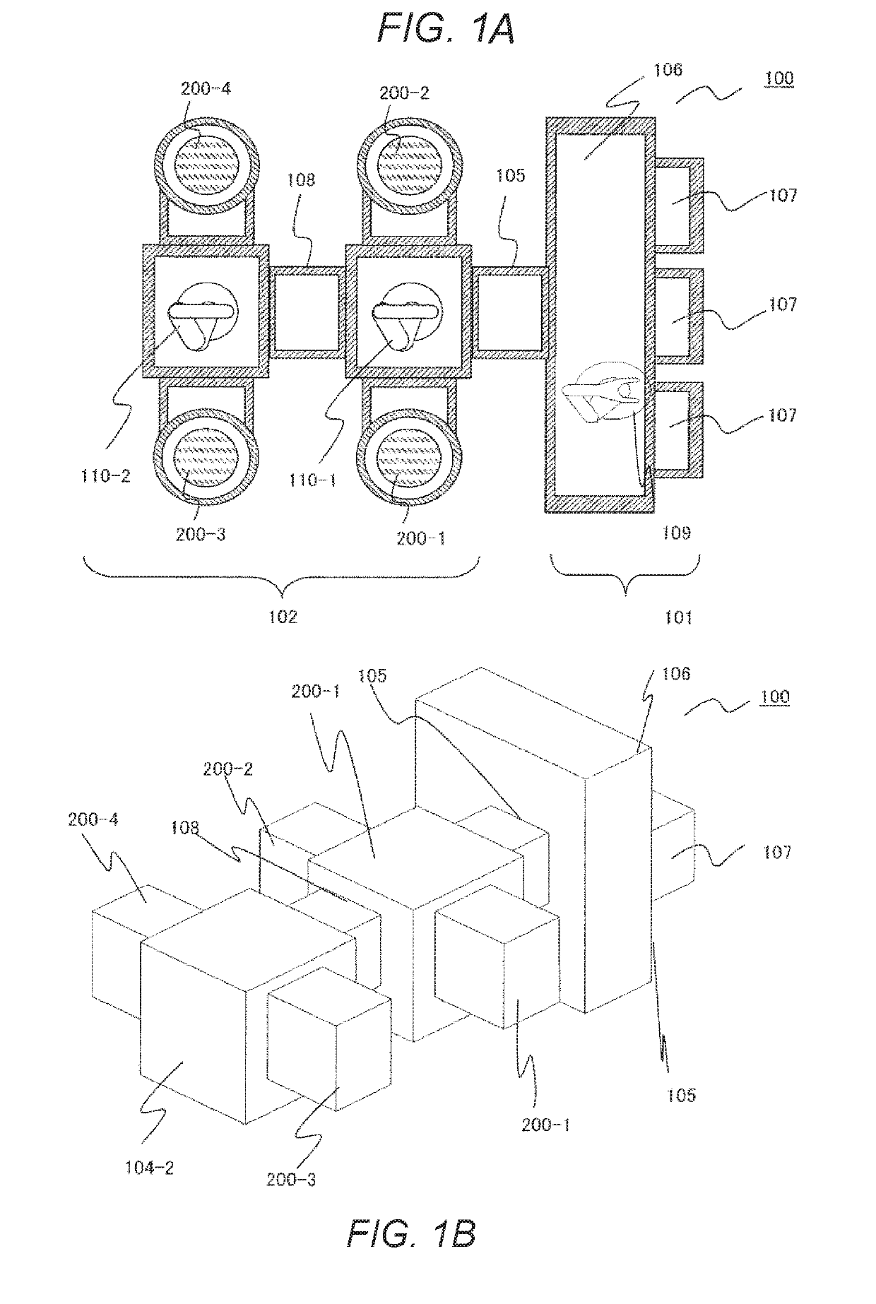
[0051]FIG. 1 is a view schematically illustrating a schematic configuration of a vacuum processing apparatus according to an embodiment of the invention. FIG. 1A is a cross-sectional view of a vacuum processing apparatus 100 according to the embodiment when viewed from above, and FIG. 1B is a perspective view illustrating a configuration of the vacuum processing apparatus 100.

[0052]The vacuum processing apparatus 100 of the embodiment includes an atmospheric block 101 disposed on a front side (right upper side in the drawing) and a vacuum block 102 disposed on a rear side (left upper side in the drawing). The atmospheric block 101 is a part to which ...


PUM


Abstract

There is provided a vacuum processing apparatus in which at least one of the processing units includes a lower member and an upper member mounted on the lower member to be attachable and detachable that configure the vacuum container, a turning shaft member which is attached to an outer circumferential part of the base plate between the work space and the vacuum container, and has a turning shaft that moves from above the base plate when the turning shaft is connected to the lower member and the lower member turns around the connected part, and a maintenance member including an arm which is disposed above the turning shaft member and turns in a horizontal direction as the upper member is suspended, and in which the lower member is configured to be fixable at the position at a predetermined angle within a range of an angle at which the lower member is capable of turning around the shaft, and to be vertically movable as the arm of the maintenance member fixes the position above a center portion of the lower member of which the position is fixed within a range of the angle at which the lower member is capable of turning, and the upper member is suspended.

Description

CROSS-REFERENCE TO RELATED APPLICATIONS[0001]The present application claims priority to Japanese Patent Application No. 2017-221441, filed Nov. 17, 2017. The contents of this application are incorporated herein by reference in their entirety.BACKGROUND OF THE INVENTIONField of the Invention[0002]The present invention relates to a vacuum processing apparatus for processing a substrate-like sample, such as a semiconductor wafer transported and disposed in a decompressed processing chamber on the inside of a vacuum container by using plasma formed in the processing chamber, and to a vacuum processing apparatus including a plurality of members which are disposed to be attachable and detachable at a position in an upward-and-downward direction and configure the vacuum container.Background Art[0003]As a semiconductor wafer manufacturing apparatus for manufacturing a semiconductor device from a substrate-like sample, such as a semiconductor wafer, an apparatus which performs processing, su...

Claims


Application Information

Patent Timeline
IPC IPC(8): H01J37/32H01L21/677H01J37/18H01J37/34H01L21/67H01L21/687
CPCH01J37/32862H01L21/6776H01J37/185H01J37/3491H01J37/32743H01L21/67259H01L21/68707H01L21/6704H01L21/67184H01L21/6719H01L21/67748H01J37/32889H01L21/67069H01L21/6715H01L21/67742H01L21/67772H01L21/3065H01L21/02315
Inventor ISOMURA, RYOICHISAKKA, YUUSAKUSATOU, KOUHEIUEMURA, TAKASHIYAMAMOTO, SATOSHIKAWASAKI, HIROMICHI
Owner HITACHI HIGH-TECH CORP
Why Eureka
Try Eureka