
Storage control apparatus and managment method for semiconductor-type storage device

a storage device and control apparatus technology, applied in the direction of memory architecture accessing/allocation, instruments, computing, etc., can solve the problems of reaching the upper limit of erased number, write error or read error in flash memory, etc., to improve the efficiency of maintenance work and perform maintenance work systematically.

Inactive Publication Date: 2012-11-22
HITACHI LTD
View PDF3 Cites 11 Cited by
  • Summary
  • Abstract
  • Description
  • Claims
  • Application Information

AI Technical Summary

Benefits of technology

[0007]In a case where the lifetime of a storage device suddenly ends one day, it is not possible to erase the data stored in this storage device by sending the storage device an erase command. In this case, the data stored in this storage device is prevented from leaking outside by physically destroying the storage device whose lifetime ended. Physically destroying the storage device makes it impossible to reuse the relatively expensive flash memory, increasing operating costs.
[0009]With the foregoing problems in view, an object of the present invention is to provide a storage control apparatus and a management method for a semiconductor-type storage device for enabling maintenance work to be performed systematically. Another object of the present invention is to provide a storage control apparatus and a management method for a semiconductor-type storage device for enabling maintenance to be performed systematically on multiple storage devices having different lifetimes, and for making it possible to improve the efficiency of maintenance work.Solution to Problem

Problems solved by technology

Either a write error or a read error can occur in a flash memory, which has reached the upper limit for number of erases.

Method used


Image

  • Storage control apparatus and managment method for semiconductor-type storage device
  • Storage control apparatus and managment method for semiconductor-type storage device
  • Storage control apparatus and managment method for semiconductor-type storage device

Examples


example 1

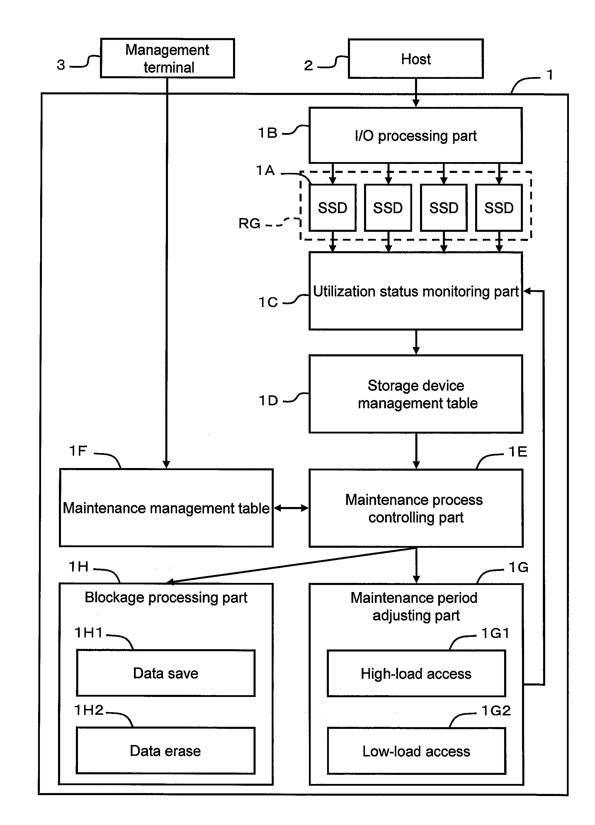
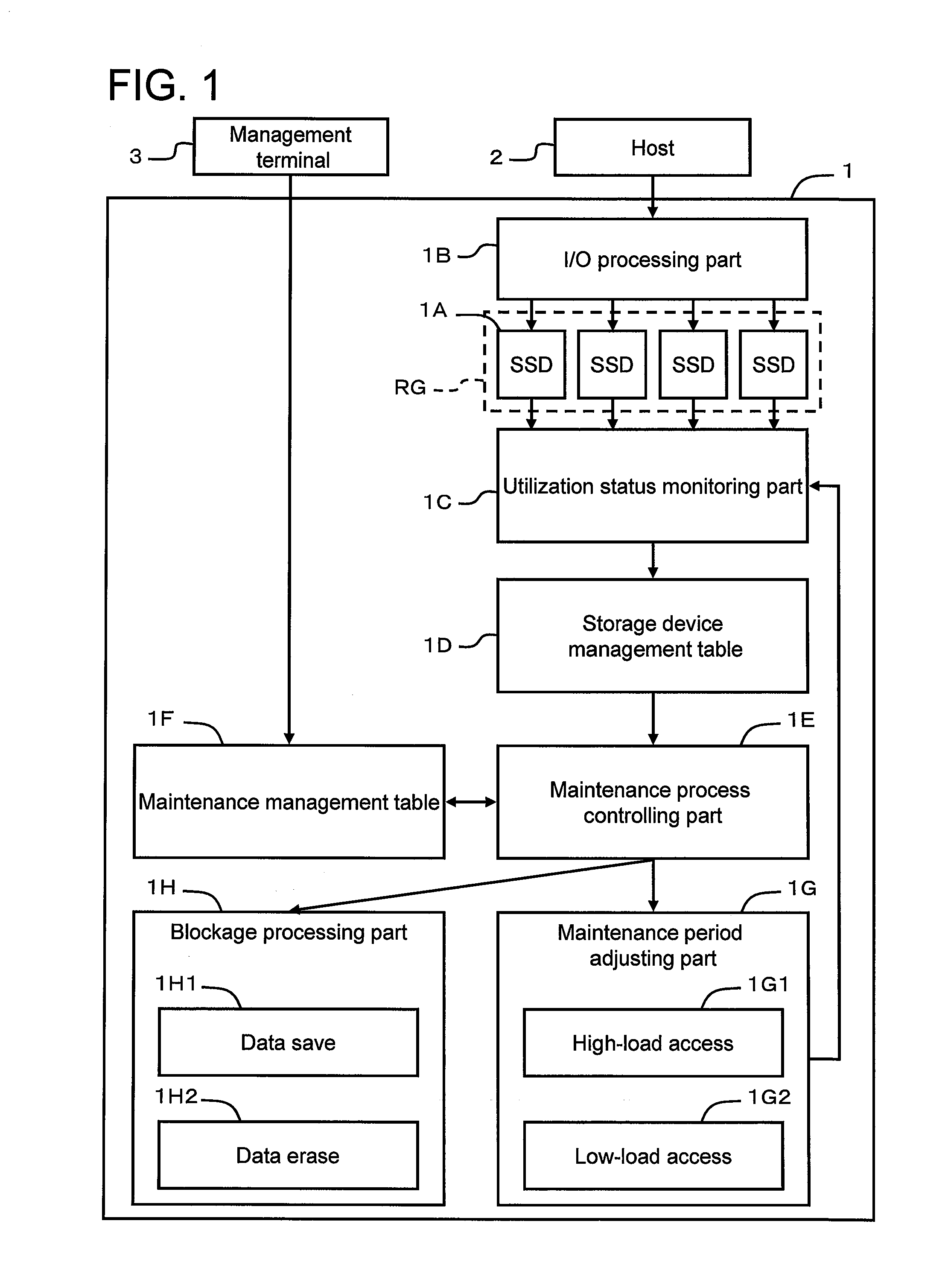
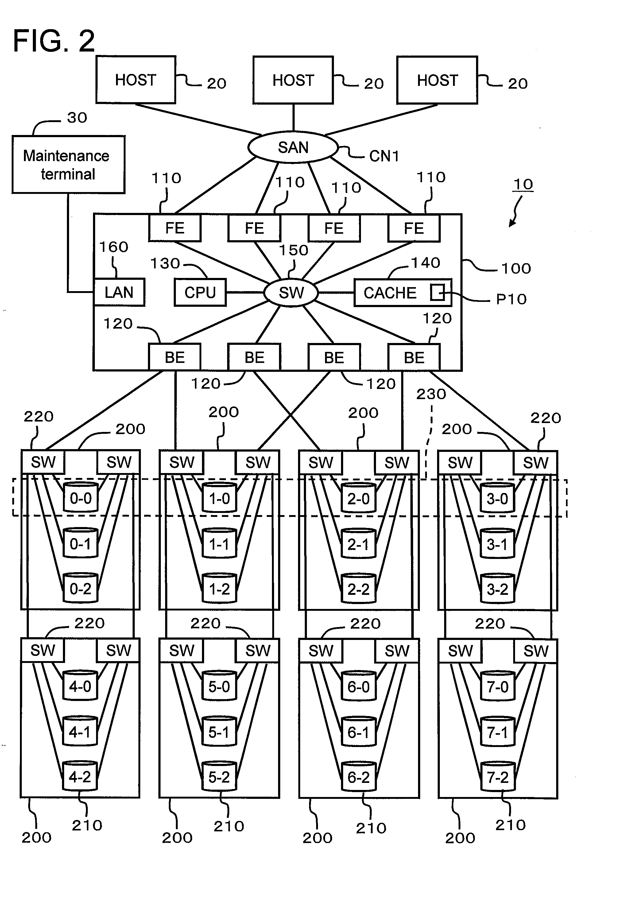
[0067]A first example will be explained by referring to FIGS. 2 through 21. First, by way of describing the relationship with FIG. 1, the storage control apparatus 10 corresponds to the storage control apparatus 1 of FIG. 1, the host 20 corresponds to the host 2 of FIG. 1, the maintenance terminal 30 corresponds to the management terminal 3 of FIG. 1, and the storage device 210 corresponds to the storage device 1A of FIG. 1. The controller 100 of FIG. 2 realizes the respective functions (or management information) 1B, 1C, 1D, 1E, 1F, 1G and 1H of FIG. 1.

[0068]As shown in the block diagram of the entire computer system of FIG. 2, the computer system, for example, comprises at least one storage control apparatus 10, at least one host 20, and at least one maintenance terminal 30. The storage control apparatus 10 and the respective hosts 20, for example, are coupled via a communication network CN1 like either a FC-SAN (Fibre Channel-Storage Area Network) or an IP-SAN (Internet Protocol-...

example 2

[0186]A second example will be explained by referring to FIGS. 22 and 23. Since this example is equivalent to a variation of the first example, the explanation will focus on the differences with the first example. In this example, an adjustment will be explained in a case where subsequent to an access control process being started for one storage device 210 another access control process is started for another storage device 210.

[0187]FIG. 22 is a flowchart of an access control process in accordance with this example. This process comprises all of Steps S50 through S56 of the processing shown in FIG. 16. In addition, new Steps S90 and S91 are disposed between S53 and S54 in this process. Consequently, the new Steps S90 and S91 will be explained.

[0188]The controller 100, upon making a determination that it is necessary to execute the access control process (S53: YES), determines whether or not another storage device for which the access control process is already being executed exist...


PUM


Abstract

The present invention is provided for maintaining and replacing storage devices systematically in accordance with schedule. A storage control apparatus 1 has multiple storage devices 1A equipped with flash memory or the like. The storage control apparatus 1 monitors and records the utilization state of each storage device. When a storage device utilization state reaches a first threshold, the storage control apparatus starts an access control process to control the length of a maintenance period. When the storage device utilization state reaches a second threshold, the storage control apparatus executes blockage control, thereby causing this storage device to be replaced. The timing, at which a storage device with little lifetime remaining is replaced, is controlled to enhance maintenance work efficiency.

Description

TECHNICAL FIELD[0001]The present invention relates to a storage control apparatus and a management method for a semiconductor-type storage device.BACKGROUND ART[0002]A storage control apparatus, which controls multiple storage devices, for example, provides a host computer with a storage area based on RAID (Redundant Arrays of Inexpensive Disks). Hard disk drives are well known as storage devices, but a storage device (Solid State Drive) using flash memory have been introduced in recent years.[0003]The flash memory is able to read and write data, and, in addition, will not lose data even when the power supply is shut off. The flash memory writes data in page units, and erases data in block units. The block unit is larger than the size of the page. The flash memory has limits with respect to number of erases and number of writes in accordance with the type of this memory. Either a write error or a read error can occur in a flash memory, which has reached the upper limit for number of...

Claims


Application Information

Patent Timeline
Patent Type & Authority Applications(United States)
IPC IPC(8): G06F12/00
CPCG06F12/0246G06F2212/1036G06F2212/7211G06F2212/262G06F2212/7208G06F2212/1052
Inventor KOIZUMI, YOSHIHARUHONDA, KIYOSHISASAKI, KAZUSHIUCHIDA, KEIICHIRO
Owner HITACHI LTD
Learn More