Visual inspection apparatus, visual inspection method, and peripheral edge inspection unit that can be mounted on visual inspection apparatus

A visual inspection device and visual inspection technology, which is applied in the direction of semiconductor/solid-state device testing/measurement, etc., can solve problems such as the need to hand over workpieces, and the longer production cycle time

Inactive Publication Date: 2008-04-23
OLYMPUS CORP
View PDF4 Cites 14 Cited by
  • Summary
  • Abstract
  • Description
  • Claims
  • Application Information

AI Technical Summary

Problems solved by technology

[0006] However, in order to perform macroscopic inspection, microscopic inspection, and edge portion inspection at the same time, it is necessary to use a robot arm or a loader (loader) between the appearance inspection device disclosed in Patent Document 1 and the appearance inspection device disclosed in Patent Document 2. Transferring wafers while handing over has the problem of prolonging tact time
In addition, when one visual inspection device is externally installed with another visual inspection device, the transportation time can be shortened, but in this case, it is also necessary to hand over the workpiece, etc.

Method used


Image

  • Visual inspection apparatus, visual inspection method, and peripheral edge inspection unit that can be mounted on visual inspection apparatus
  • Visual inspection apparatus, visual inspection method, and peripheral edge inspection unit that can be mounted on visual inspection apparatus
  • Visual inspection apparatus, visual inspection method, and peripheral edge inspection unit that can be mounted on visual inspection apparatus

Examples


no. 1 Embodiment approach

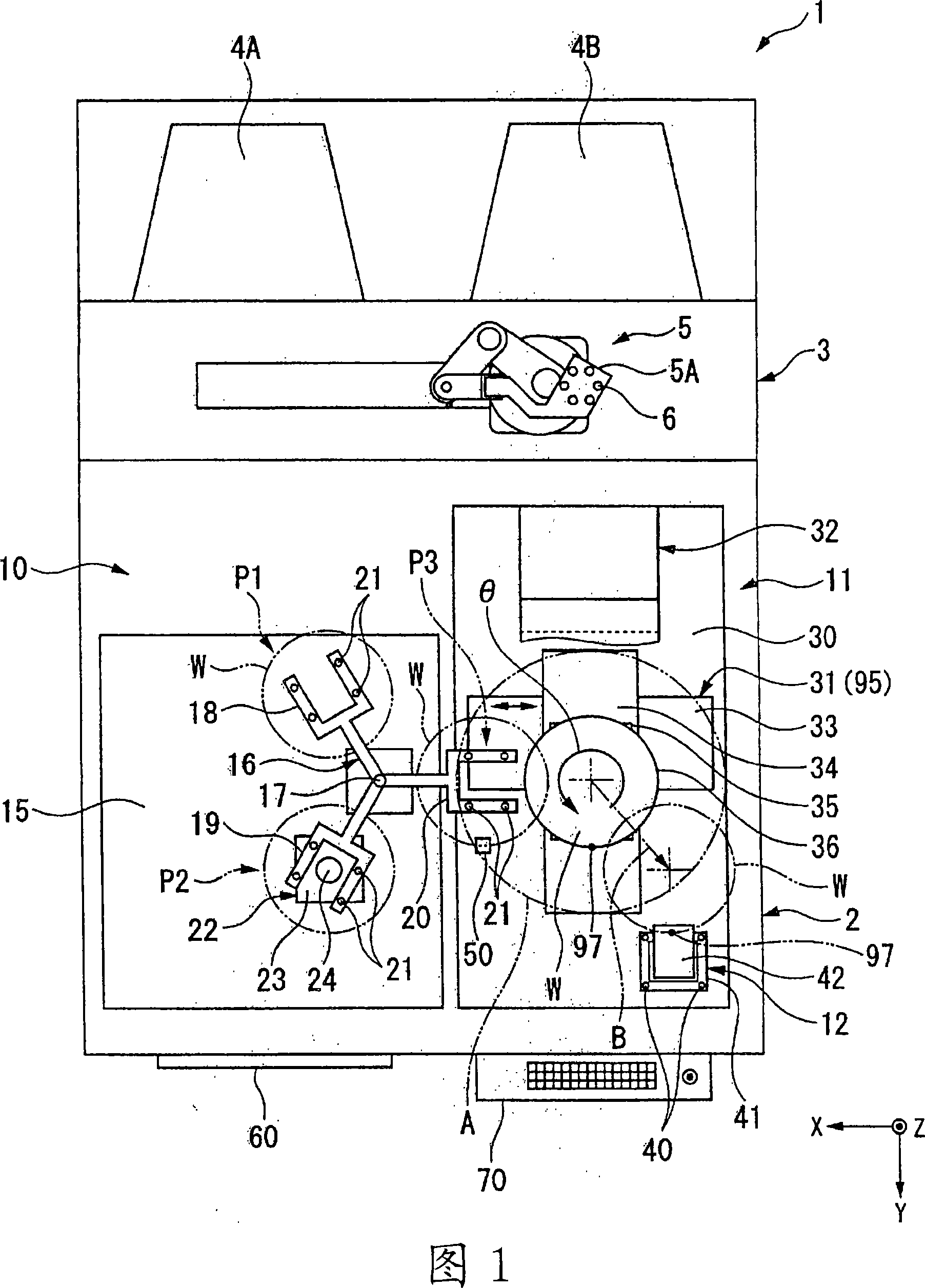
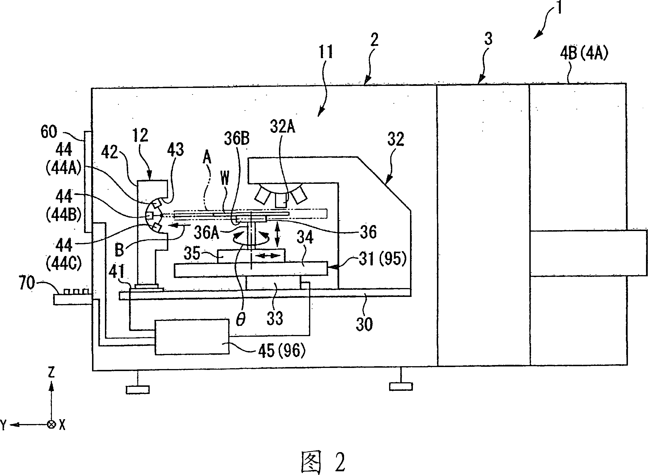
[0081] As shown in FIG. 1 , the visual inspection device 1 is provided with an inspection unit 2 on the front side (downward in FIG. 1 ) facing the inspector, and a loader unit 3 is connected to the back side of the inspection unit 2 . To the loader unit 3 , wafer trays 4A, 4B are connected in parallel, and the wafer trays 4A, 4B accommodate semiconductor wafers W (hereinafter referred to as wafers W) as workpieces. Wafer trays 4A and 4B can accommodate a plurality of wafers W at predetermined pitches in the vertical direction. For example, uninspected wafers W are accommodated on wafer tray 4A, and inspected wafers W are accommodated on wafer tray 4B. Furthermore, each wafer tray 4A, 4B can be attached to and detached from the loader unit 3 independently.

[0082] The loader unit 3 has a transport robot arm 5 . The transfer robot arm 5 is composed of a multi-joint arm, and a handle 5A at the front end thereof is provided with a suction hole 6 for sucking and holding the wafe...

no. 2 Embodiment approach

[0118] The second embodiment is characterized in that the edge inspection unit is provided on the macro inspection unit for visual inspection. Other structures and functions are the same as those of the first embodiment.

[0119] As shown in FIG. 4 , in the appearance inspection device 51 , an edge inspection unit 61 (outer edge inspection unit) is detachably provided on the mounting plate 15 of the macro inspection unit 10 . The edge inspection unit 61 has a fixing unit 62 fixed to the mounting plate 15 , a pedestal 63 , and a base unit 42 on which the enlarged image acquisition unit 44 is attached, and the base unit 42 is mounted so as to be freely accessible to and separated from the position P2. As shown in FIG. 5 , the edge portion of the wafer W horizontally held on the macro inspection unit 22 enters the recess 43 at the inspection position where the base portion 42 is closest. Also, as indicated by phantom lines, the position at which the base portion 42 is farthest a...

no. 3 Embodiment approach

[0125] The third embodiment is characterized in that an edge portion inspection unit is provided on an automatic macro inspection unit that automatically extracts defects from images captured by an imaging device by image processing. Other structures and functions are the same as those of the first embodiment.

[0126] As shown in FIGS. 6 and 7 , the visual inspection device 71 has a vibration-damped mounting plate 72 , and an automatic macroscopic inspection unit 73 is built on the mounting plate 72 . The automatic macro inspection unit 73 has an inspection table 74 , an illumination unit 75 and an imaging unit 76 fixed so as to sandwich the inspection table 74 in the X direction. The inspection table 74 is composed of an X-axis table 77 , a Z-axis table 78 , and a rotation shaft 79 as a rotation mechanism, and a holding plate 80 for absorbing and holding a wafer is fixed to the rotation shaft 79 . The illuminating unit 75 has a line light source that irradiates the upper su...


PUM


Abstract

The invention provides a visual inspection apparatus, visual inspection method, and peripheral edge inspection unit that can be mounted on visual inspection apparatus. A visual inspection apparatus is provided with a macroscopic inspecting section (10) and a microscopic inspecting section (11), and the microscopic inspecting section (11) has an inspection stage (31) and a microscope (32) on a mounting plate (30). The inspection stage (31) is movable in an X direction, a Y direction and a Z direction, and is also rotatable in a direction. Furthermore, a periphery inspecting section (12) is fixed on the mounting plate (30) for obtaining an enlarged image of a periphery of a wafer (W). The periphery inspecting section (12) is arranged to pick up an image of the periphery of the wafer (W) held by the inspection stage (31).

Description

technical field [0001] The present invention relates to an appearance inspection device for inspecting the appearance of a workpiece, an appearance inspection method, and an edge inspection unit which can be installed on the appearance inspection device for inspecting the edge of a workpiece. Background technique [0002] When forming a pattern such as a circuit on a workpiece such as a semiconductor wafer, an appearance inspection device that inspects the front surface of the workpiece for defects is used. As such an appearance inspection device, there is an appearance inspection device that holds a workpiece freely swingable and rotatable, has a macro inspection unit that allows the inspector to visually inspect the front of the workpiece (macro inspection), and obtains an enlarged image of the workpiece for inspection. (Micro-inspection) The micro-inspection section can perform macro-inspection and micro-inspection with one device (for example, see Patent Document 1). ...

Claims


Application Information

Patent Timeline
Patent Type & Authority Applications(China)
IPC IPC(8): H01L21/66
Inventor 横田敦俊蛇石广康土坂新一
Owner OLYMPUS CORP
Why Eureka
Try Eureka