Oil Free Screw Compressor

a compressor and oil-free technology, applied in the direction of machines/engines, rotary/oscillating piston pump components, liquid fuel engines, etc., can solve the problems of reducing the performance of the compressor, increasing the pressure loss, and easily leaking vibration and pulsating sound from the front surface of the cooler part, so as to reduce the installation area and reduce the noise

Active Publication Date: 2013-05-30
HITACHI IND EQUIP SYST CO LTD
View PDF4 Cites 17 Cited by
  • Summary
  • Abstract
  • Description
  • Claims
  • Application Information

AI Technical Summary

Benefits of technology

[0009]In view of the problems described above, the present subject matter has been made, and it is an object of the subject matter to provide a compact oil free screw compressor capable of reducing noise, ensuring a cooling capability of heat exchangers, and further reducing an installation area.

Problems solved by technology

In Patent Document 1 described above, the devices such as the coolers forming the cooling devices are structured to be exposed to the back surface for direct communication, thus resulting in a drawback such that vibrating sound and pulsating sound easily leak from a front surface of a cooler part.
Moreover, in Patent Document 2 described above, since the air-cooled heat exchanges (the inter cooler, the after cooler, the oil cooler, etc.) are arranged on one side isolated from the compressor main body and the driving system devices inside the package, a pipe length connecting together the compressor main body and the air-cooled heat exchangers increases and pressure loss increases, thus leading to performance deterioration of the compressor.
Moreover, the pipe length increase results in an increase in noise generated by pipe vibration and also a disadvantageous structure in terms costs.

Method used


Image

  • Oil Free Screw Compressor
  • Oil Free Screw Compressor
  • Oil Free Screw Compressor

Examples


Embodiment Construction

[0019]In the following detailed description, numerous specific details are set forth by way of examples in order to provide a thorough understanding of the relevant teachings. However, it should be apparent to those skilled in the art that the present teachings may be practiced without such details. In other instances, well known methods, procedures, components, and / or circuitry have been described at a relatively high-level, without detail, in order to avoid unnecessarily obscuring aspects of the present teachings.

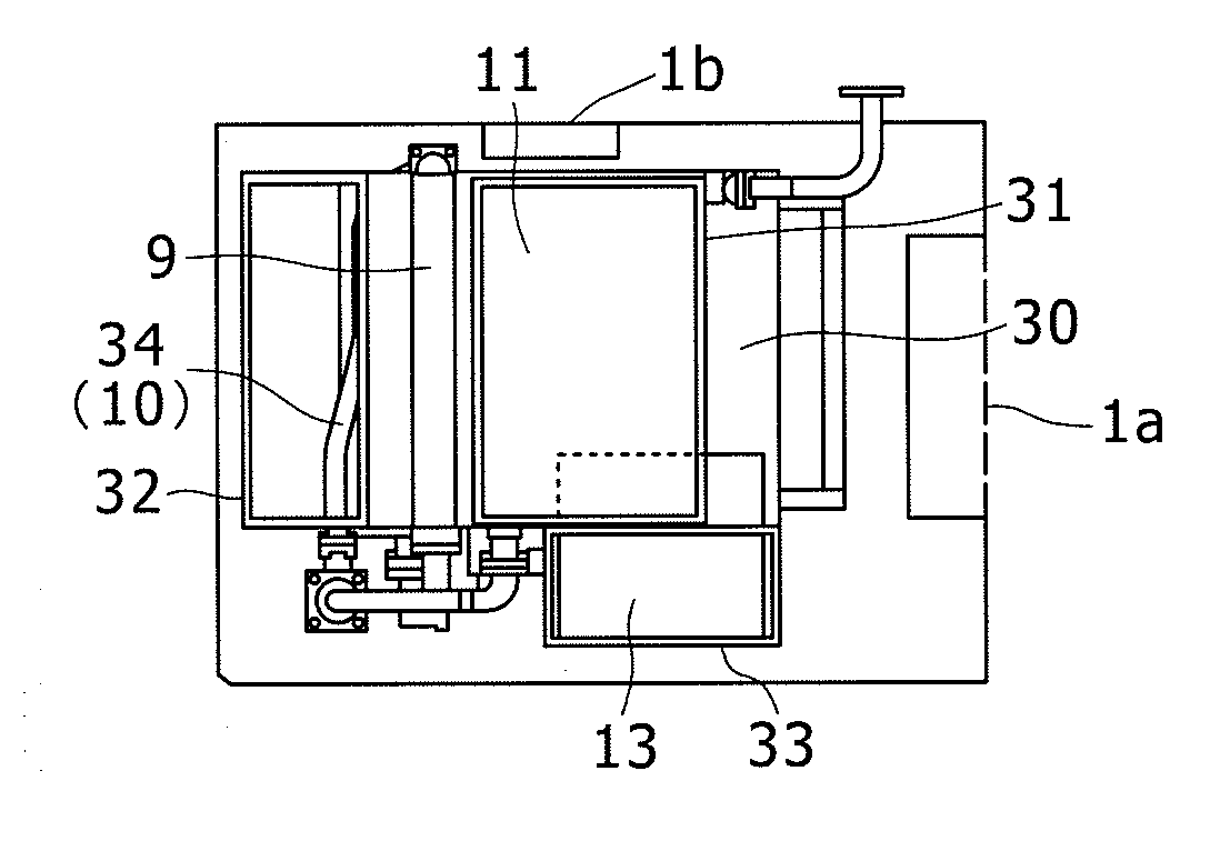
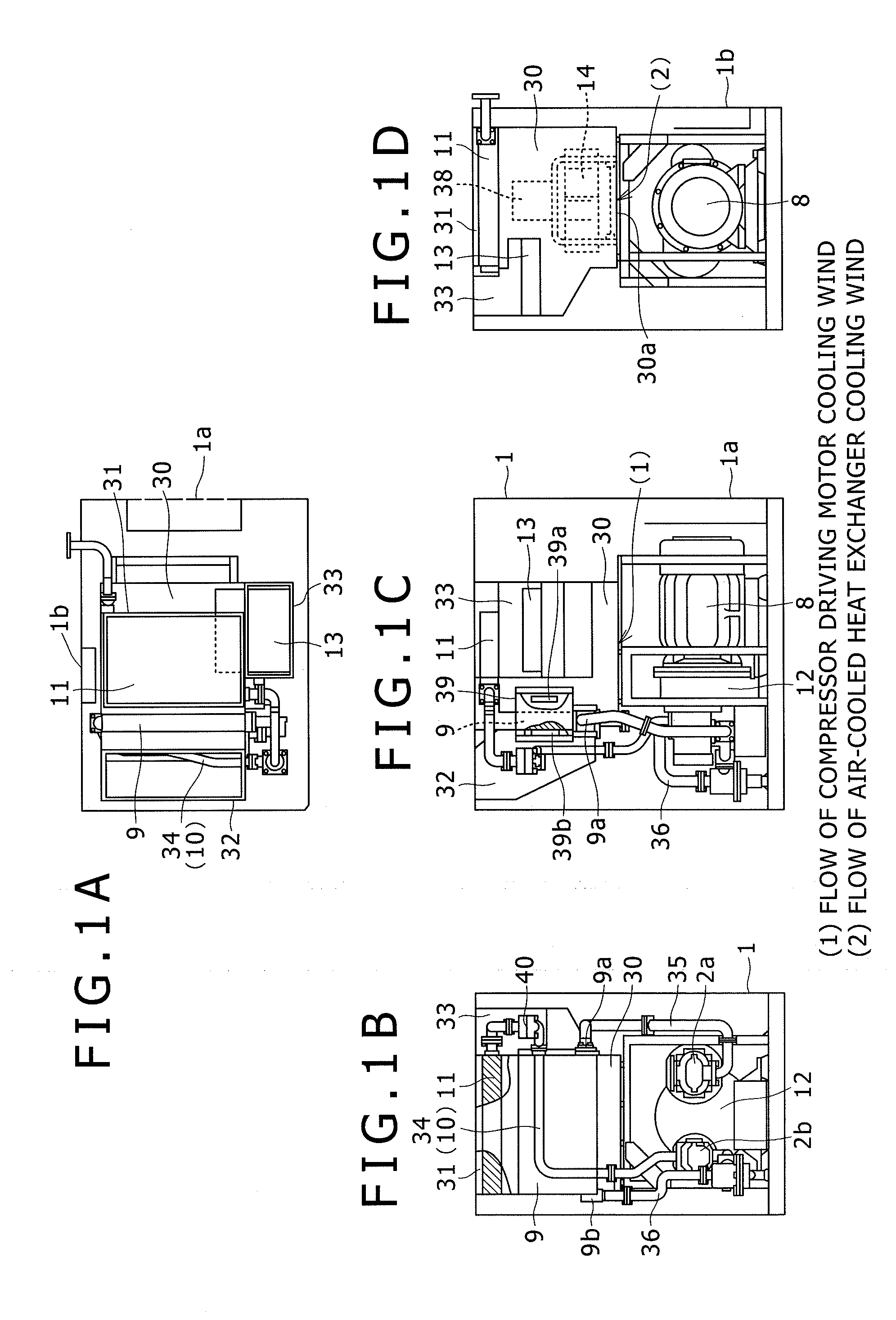
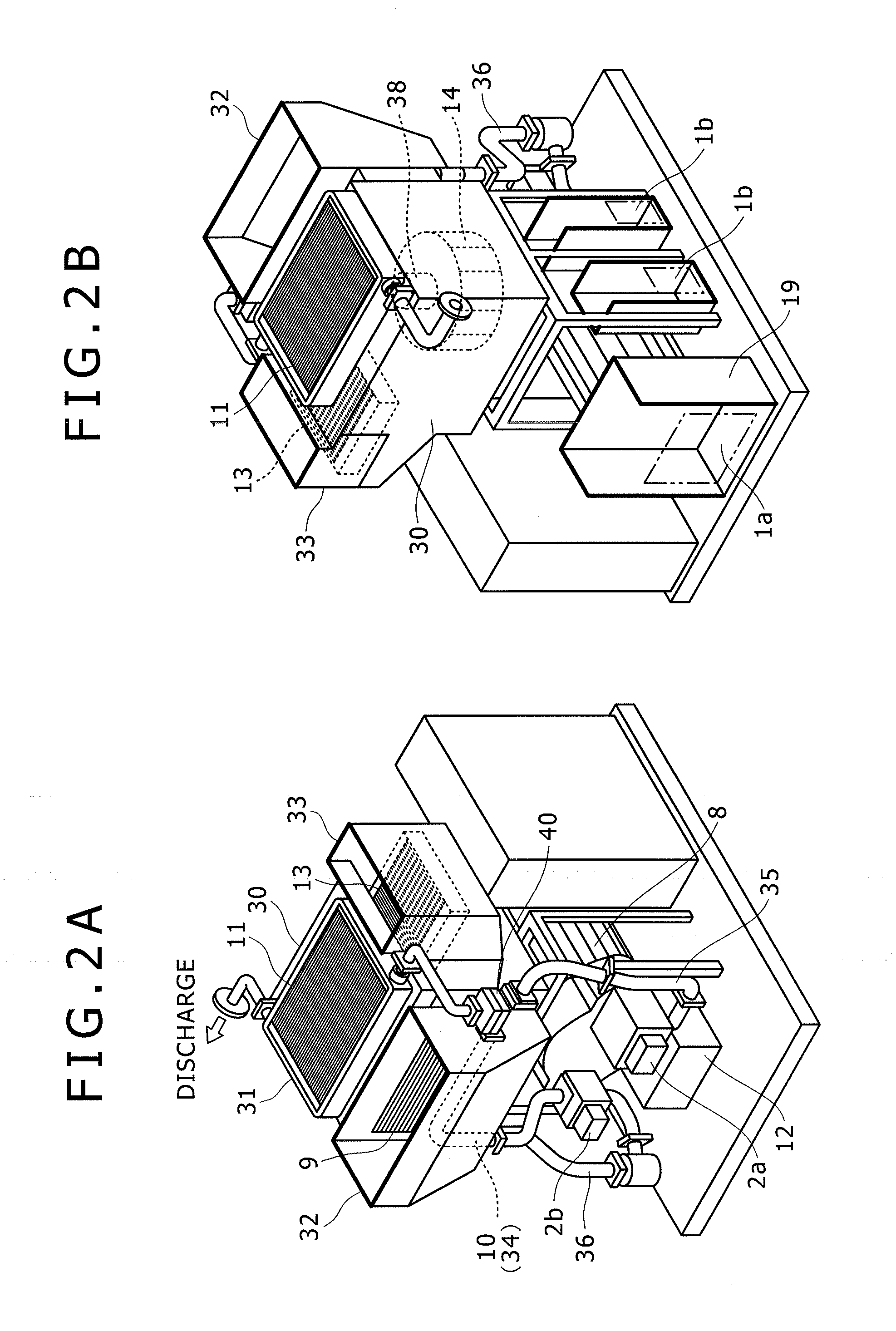
[0020]An embodiment of the present subject matter will be described, referring to as an example a package-type oil free screw compressor including a low-pressure stage compressor main body and a high-pressure stage compressor main body.

[0021]FIGS. 1A to 1D, 2A and 2B are unit structure diagrams of the oil free screw compressor according to the embodiment. FIG. 3 is a diagram showing a structure and flows of compressed air and lubricating oil of the oil free screw compress...


PUM


Abstract

Provided are a structure of arranging a compressor main body and a compressor driving motor at a bottom of a package; including a duct on a top side thereof; arranging an inter cooler on a left side surface of the duct; arranging an after cooler on a top surface thereof; arranging an oil cooler on a front surface thereof; arranging a cooling fan inside of the duct; providing an exhaust port on a bottom surface of the duct; and respectively providing exhaust ducts connected to a top surface of the package on downstream sides of the coolers, and a structure of cooling air suctioned by the cooling fan from the suction port to the inside of the duct, passing through the coolers, and discharged upwardly from the package via the exhaust duct, implementing a compact oil free screw compressor with low noise capable of reducing an installation area.

Description

[0001]This application claims the priority of Japanese Patent Application No. JP 2011-261182, filed Nov. 30, 2011, the disclosure of which is expressly incorporated by reference herein in its entirety.TECHNICAL FIELD[0002]The present subject matter relates to a package-type oil free screw compressor.BACKGROUND[0003]Patent Document 1 describes one example of a conventional oil free screw compressor. In this conventional one, cooling devices such as air-cooled heat exchangers (an inter cooler, an after cooler, an oil cooler, etc.) are arranged on a back surface of a compressor main body or driving system devices (a motor, a gear casing, etc.). The coolers forming the cooling devices are so arranged as to be exposed to a back surface of the package to take outside air at low temperature directly into the coolers, thereby achieving downsizing of the coolers.[0004]Moreover, in a conventional art described in Patent Document 2, air-cooled heat exchangers (an inter cooler, an after cooler,...

Claims


Application Information

Patent Timeline
Patent Type & Authority Applications(United States)
IPC IPC(8): F01C21/06
CPCF04C29/04F04C29/02F01C21/007F04C18/16
Inventor YABE, TOSHIAKIKAWABATA, NATSUKIOKAYA, MASAKATSUSAKAI, KOHEI
Owner HITACHI IND EQUIP SYST CO LTD
Why Eureka
Try Eureka