Composite material and production method thereof
A composite material and reinforcing material technology, applied in the field of internal structure of parts, can solve the problem that 3D-bulk orientation strength cannot be predetermined and so on
- Summary
- Abstract
- Description
- Claims
- Application Information
AI Technical Summary
Problems solved by technology
Method used
Image
Examples
Embodiment approach 1
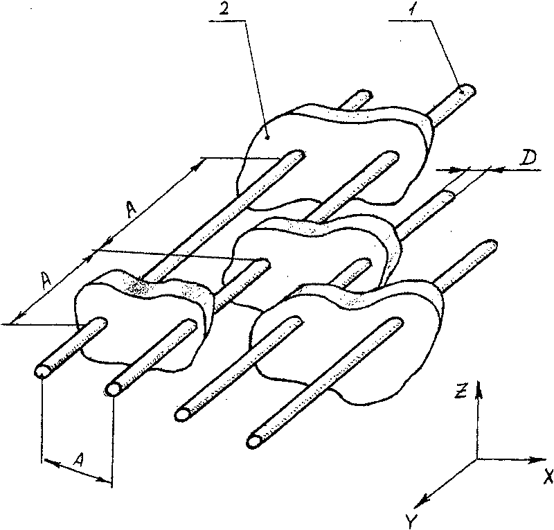
[0051] Such as figure 1 As shown in , this embodiment consists of component segments with unidirectionally oriented strands 1 of reinforcement material, supported by connections 2 between the strands. The distance A between the determined connection points is equal to (or smaller than) the Euler critical length. This configuration of the material resists the compressive forces exerted on the wire 1 and prevents buckling in the direction of the X-axis. That is, the wire cross-section (and corresponding weight) required to withstand compressive forces in the Z direction is drastically reduced (by as much as 5-100 times) compared to a solid wall construction of equivalent flexural resistance . That is, resistance to compressive forces in the Z direction achieves strength suitable for wire compression. In this case, the additional weight at the connection point 2 may be 5-20 times smaller than the weight of the solid bonding material connected proportionally to the critical len...
Embodiment approach 2
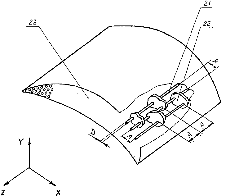
[0053] figure 2 A component segment structure formed from dense unidirectional mold-filled boron wires 21 is represented. The line 21 connected to the connection point 22 is produced by using ammonium supply at a temperature in excess of 800°C. Subsequently, the lines connected between them and on the outer surface 23 create a protective layer of boron nitride. The construction must withstand tension in the Z direction (centrifugal force), bending in the X & Y directions (gas pressure), and the possibility of a separate external wire on the side opposite to the direction of the gas pressure because of the gas force of the bend. A preferred form of such component construction for this application (turbine blade) may be constructed as follows:
[0054] 1. Unidirectional boron can withstand a higher force (for boron protected by boron nitride) at a high temperature of 1150°C, that is, an increase of 250-300°C. An increase in turbine blade temperature would lead to an increas...
Embodiment approach 3
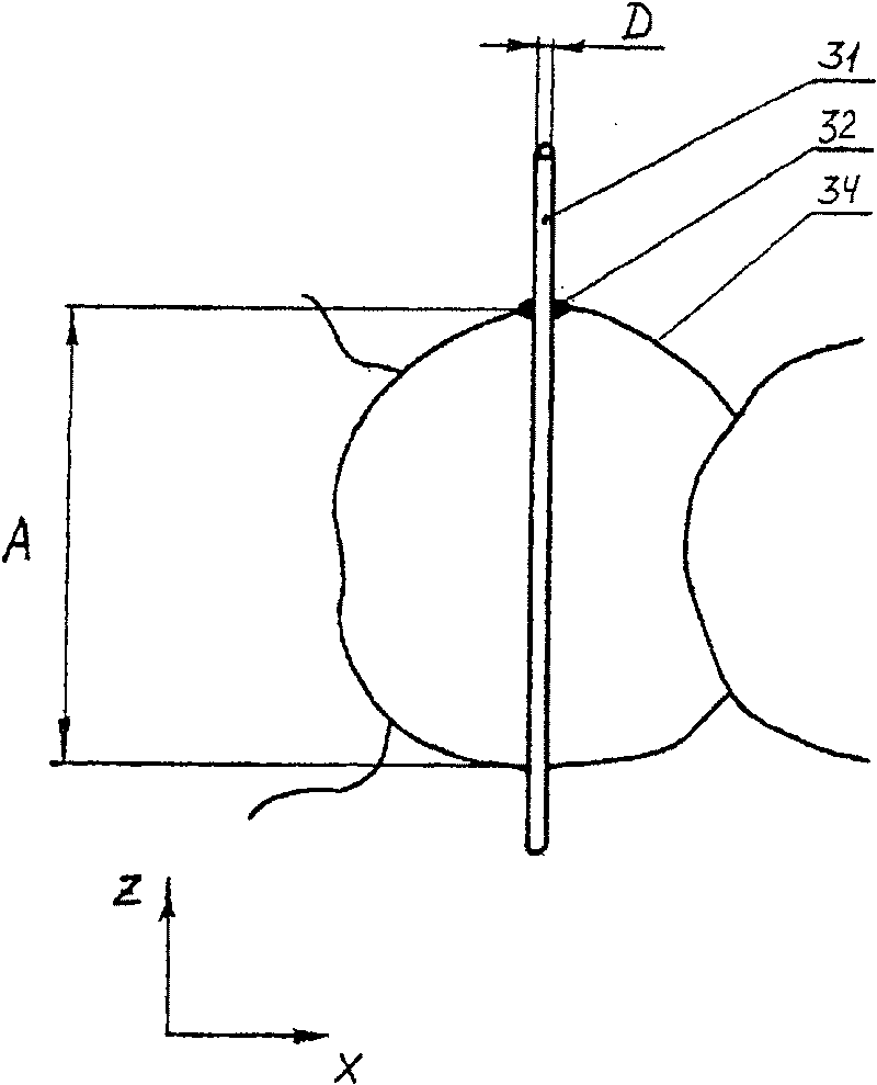
[0062] image 3 Is a part fragment cross-sectional view showing the structure of a single oriented reinforcement thread supported by a bond material with a foam structure. Such as image 3 As shown in , the present embodiment consists of strands 31 of unidirectional reinforcing material supported by connection points 32 and housing walls 34 filled with gas between the strands. The distance A between the defined connection points is equal to (or below) the critical (Euler) length-Young's modulus and the wire diameter D for this type of material. This configuration resists compressive forces applied to the wire 31 and prevents buckling in the directions of the X-axis and Y-axis. That is, the wire cross-section (and corresponding weight) required to withstand compressive forces in the Z direction is drastically reduced (by as much as 5-100 times ). That is, the resistance to compressive force in the Z direction may have the compressive strength of the wire. In this case, t...
PUM
| Property | Measurement | Unit |
|---|---|---|
| density | aaaaa | aaaaa |
| density | aaaaa | aaaaa |
| tensile strength | aaaaa | aaaaa |
Abstract
Description
Claims
Application Information
 - R&D
- Intellectual Property
- Life Sciences
- Materials
- Tech Scout
- Unparalleled Data Quality
- Higher Quality Content
- 60% Fewer Hallucinations
Browse by: Latest US Patents, China's latest patents, Technical Efficacy Thesaurus, Application Domain, Technology Topic, Popular Technical Reports.
© 2025 PatSnap. All rights reserved.Legal|Privacy policy|Modern Slavery Act Transparency Statement|Sitemap|About US| Contact US: help@patsnap.com


