Vacuum cleaner

A technology for vacuum cleaners and components, which is applied in the direction of vacuum cleaners, DC motor speed/torque control, and installation of electrical equipment. It can solve problems such as loss, work related to boost conversion circuits in the state of no open load, and power loss. Use time, effect of improving dust suction performance

Inactive Publication Date: 2004-05-19
TOSHIBA TEC KK
View PDF2 Cites 6 Cited by
  • Summary
  • Abstract
  • Description
  • Claims
  • Application Information

AI Technical Summary

Problems solved by technology

[0009] In a vacuum cleaner equipped with a step-up conversion circuit, it is known that there is a disadvantage in that power loss occurs due to switching elements of the step-up circuit during the voltage boosting process when the step-up conversion circuit is operated.
[0010] Therefore, in order to improve the dust suction performance and prolong the use time of each charge of the battery, it is necessary to make the boost conversion circuit work effectively according to the load state of the vacuum cleaner to overcome the above-mentioned shortcomings such as power loss.
[0011] However, in the technology described in the above-mentioned JP8-224198, it is only described that the power supply of the electric power supplied to the vacuum cleaner is equipped with a switching part that switches the power supply of the electric power supplied to the vacuum cleaner to one of the commercial power supply and the secondary battery. The ground is raised from a low voltage to a specified voltage without disclosing the status of the load and the operation of the boost converter circuit

Method used


Image

  • Vacuum cleaner
  • Vacuum cleaner
  • Vacuum cleaner

Examples


Embodiment Construction

[0032] Next, a first embodiment of the present invention will be described with reference to FIGS. 1 to 17. FIG.

[0033] [structure appearance]

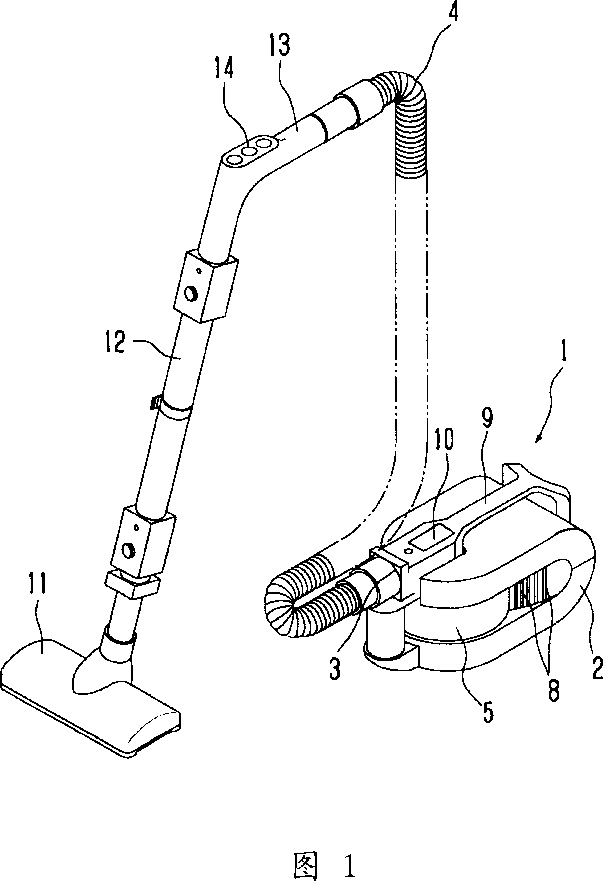
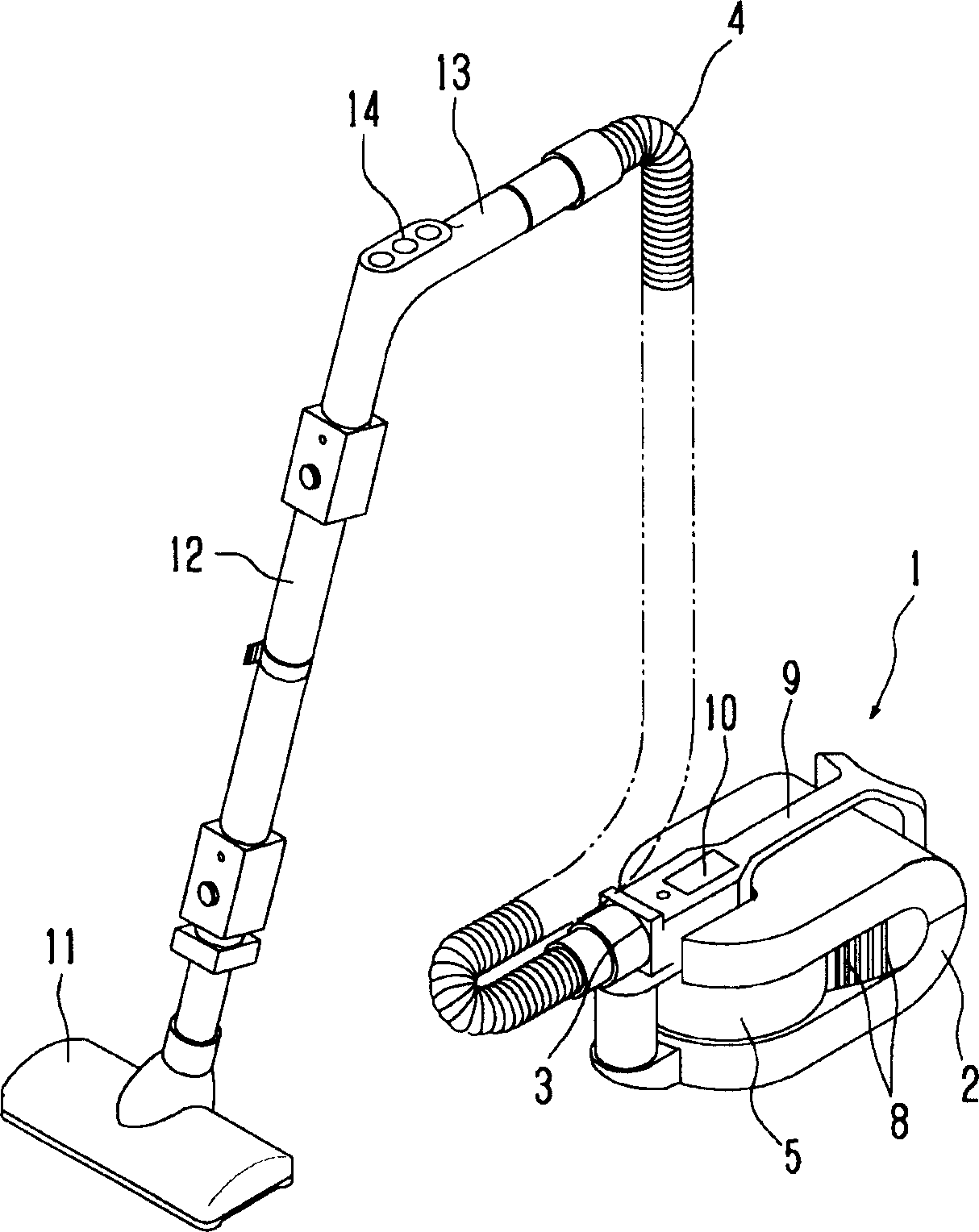
[0034] Fig. 1 is a perspective view showing the appearance structure of a vacuum cleaner according to an embodiment of the present invention. As shown in FIG. 1 , the vacuum cleaner 1 of this embodiment is provided with a detachable hose body 4 facing the suction port 3 provided on the body 2 .

[0035] Inside the body 2, a dust cup 5 serving as a dust collection chamber, an electric blower 6, and a DC power supply 7 are provided (see FIG. 2 ). On the side plate portion of the body 2 , a plurality of exhaust ports 8 opening substantially facing the front side of the communicating electric blower 6 are penetratingly provided. In the upper surface of the body 2, a handle 9 as a handle member is provided. The handle 9 is a slightly Y-shaped structure viewed from a plane. In the vicinity of the handle 9, a display unit 10 including ...


PUM


Abstract

The present invention provides an electric vacuum cleaner equipped with a step-up converter circuit with a DC power supply as a drive source, which drives and controls the step-up converter circuit so as to refer to such a relationship as to decrease a variation in dust suction capability, determine an output voltage to be boosted according to the state of a load on a motor-driven blower, boost the output voltage, based on the result of determination and supply power to the motor-driven blower, thereby activating the step-up converter circuit with satisfactory efficiency. Thus, the dust suction performance of the electric vacuum cleaner is enhanced and the usage time of a battery per charge is lengthened.

Description

technical field [0001] The present invention relates to a vacuum cleaner, in particular to a battery type vacuum cleaner. Background technique [0002] In a battery-type vacuum cleaner equipped with an electric blower, as a method of increasing the output of the electric blower to increase the dust suction capability, the general method is to increase the input to the electric blower. Specifically, there is a method of changing the winding of the electric blower, increasing the input current to the electric blower, and increasing the power supply voltage to increase the input to the electric blower. [0003] When the electric blower is composed of a commutator motor, if the input current is increased in this way, the carbon in the carbon brush part of the commutator will be worn away, and the carbon brush part will be easily damaged due to sparking in the commutator. Therefore, it is difficult to ensure reliability. [0004] In the case of a battery-type vacuum cleaner, in...

Claims


Application Information

Patent Timeline
Patent Type & Authority Applications(China)
IPC IPC(8): A47L9/28H02P7/292
CPCA47L9/2831A47L9/2884A47L9/2857A47L9/2842A47L9/2821
Inventor 栉田博之樱井修
Owner TOSHIBA TEC KK
Why Eureka
Try Eureka