Cut-off removed device

A technology of suction device and cutting roller, which is applied in metal processing and other directions, and can solve problems such as unsuitability for high-speed operation

Inactive Publication Date: 2004-05-19
ZUIKO CORP
View PDF3 Cites 6 Cited by
  • Summary
  • Abstract
  • Description
  • Claims
  • Application Information

AI Technical Summary

Problems solved by technology

The structure of the prior art is not suitable for high-speed operation because the conveying roller that absorbs and receives sanitary products is circumscribed and rotates with the cutting roller

Method used


Image

  • Cut-off removed device
  • Cut-off removed device
  • Cut-off removed device

Examples


Embodiment Construction

[0024] Hereinafter, an embodiment of the present invention will be described with reference to the drawings.

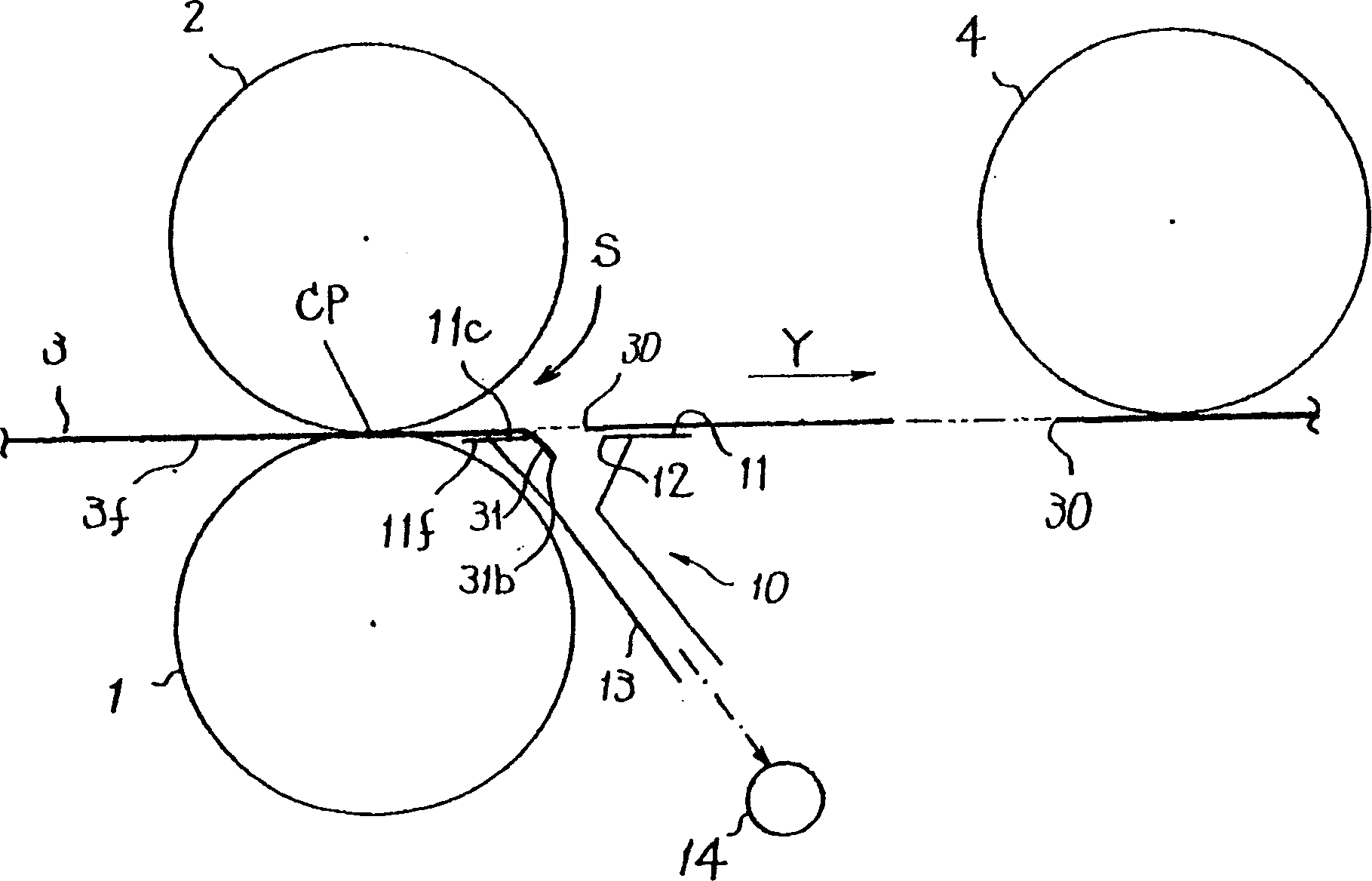
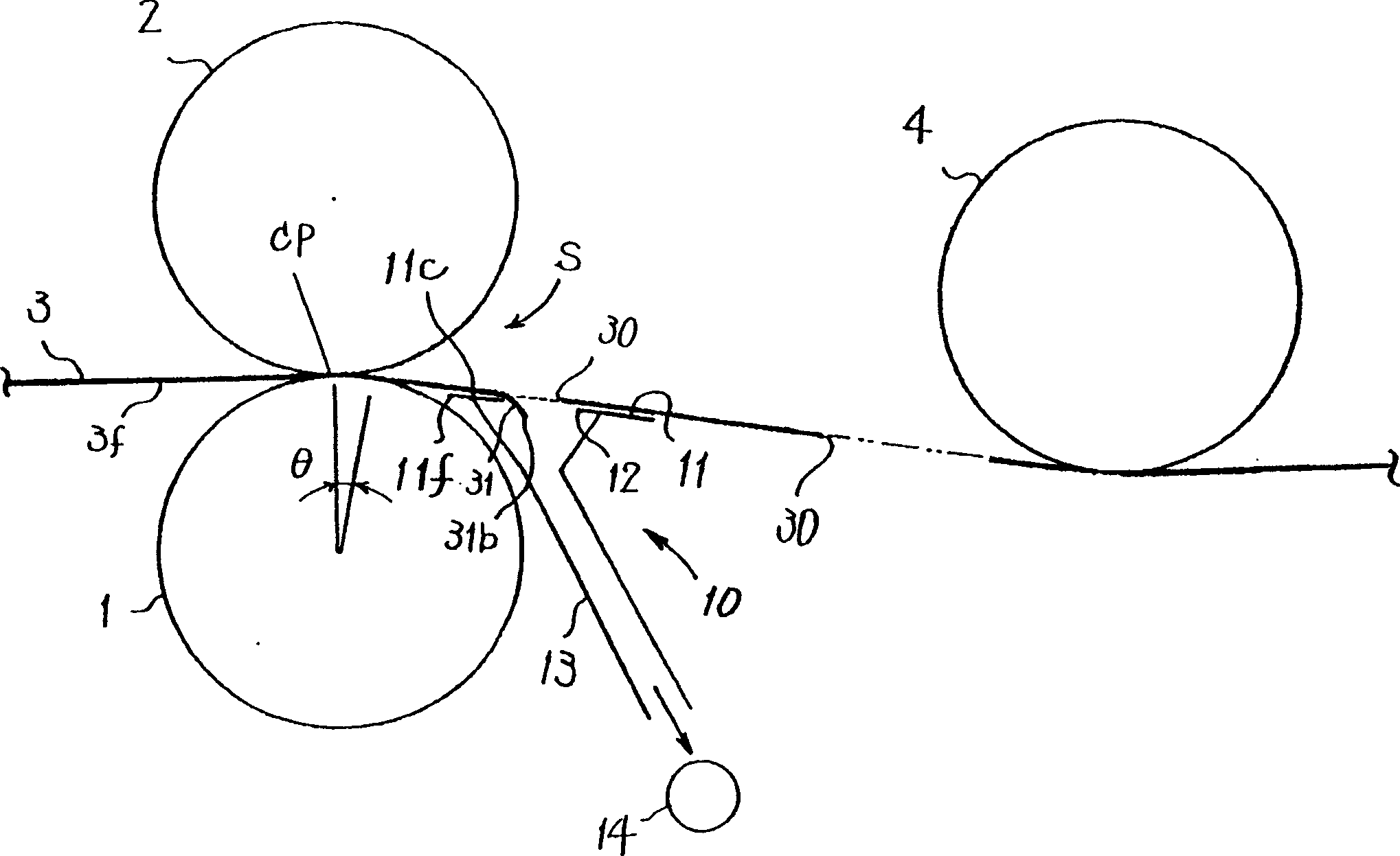
[0025] figure 1 In the process, a strip (sheet) 3 is continuously supplied between an anvil roll 1 and a cutting roll 2 . When the strip material 3 passes between the cutting roll 2 and the anvil roll 1, the strip material 3 removes the predetermined cutting and removal portion 31, and the through holes 30 are formed at predetermined pitches. The removed portion 31 is sucked by the downstream suction device 10 as will be described later.

[0026] The cutter roll 2 is disposed at a position circumscribing the anvil roll 1 .

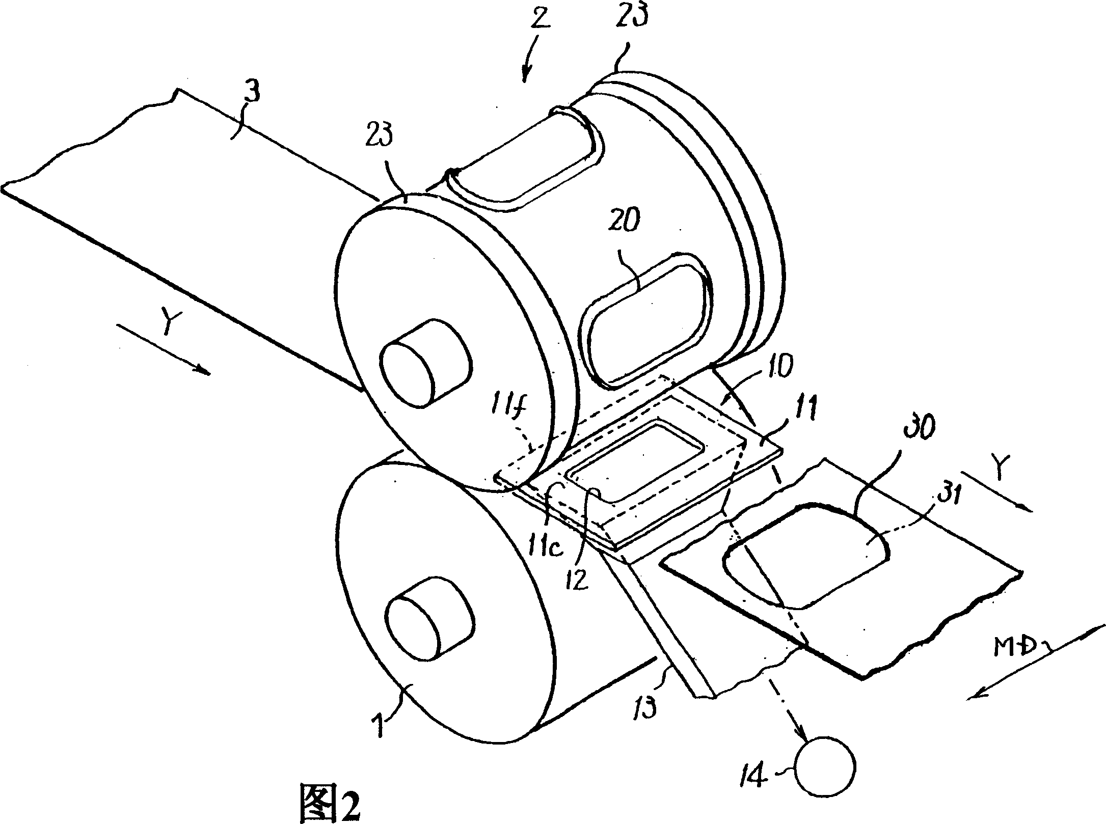
[0027] In addition, in this embodiment, the flange portion 23 having a large diameter formed on the cutter roll 2 shown in FIG. 2 is circumscribed on the anvil roll 1 . The flange portion 23 is for stabilizing the rotation of the cutting roller 2 and protecting the blade 20 .

[0028] As shown in FIG. 2 , the cutting roller 2 has, for example,...


PUM


Abstract

Provided is a cutting and removing device with a high availability factor, which smoothly cuts a sheet-like product and performs high speed operation. The cutting and removing device is provided with an anvil roll 1, a cutter roll 2, a blade 20 provided to the cutter roll 2, a suction unit 10, and forms a through-hole 30 at a prescribed part of the sheet-like product 3. The suction unit 10 is provided downstream of a cutting position of the both rolls 1, 2, and has a guide face 11c along a flow direction Y of the sheet-like product 3, a guide member 11 guiding the face of the sheet-like product 3 on the guide face 11c, and a opening 12 opened on a part of the guide face 11c of the guide member 11 for sucking in a cut and removed part 31 of the sheet-like product 3.

Description

technical field [0001] The present invention relates to a cutting and removing device for forming a through-hole of a predetermined shape in a single-layer or laminated sheet. Background technique [0002] As one of the methods of forming a through hole in a sheet, a method of cutting a roll called a punching blade is known (see, for example, JP-A-8-71999 and JP-A-11-188698). Cutting rolls form the sheet between the anvil rolls. [0003] However, in the prior art, since the surface of the sheet to be cut is not pressed against the surface of the anvil roll or the cutting roll, the sheet cannot be cut smoothly. In addition, there is no disclosure regarding the disposal method of the molded cutout portion after molding. If the molded cut-out parts are not discarded properly, the molded cut-out parts are accumulated in the dies of the cutter roll, etc., and therefore, frequent cleaning is required, and the operating rate of the apparatus may decrease. [0004] On the one han...

Claims


Application Information

Patent Timeline
Patent Type & Authority Applications(China)
IPC IPC(8): B26D7/18B26D1/40B26D7/00B26F1/38
Inventor 梅林丰志
Owner ZUIKO CORP
Why Eureka
Try Eureka