Lamp with mirror and image projector

An image projection and mirror technology, which is applied to reflectors, projection devices, lighting devices, etc., can solve the problem of difficulty in stable operation of image projection devices, and achieve the effect of miniaturization

Inactive Publication Date: 2004-05-19
PANASONIC CORP
View PDF1 Cites 2 Cited by
  • Summary
  • Abstract
  • Description
  • Claims
  • Application Information

AI Technical Summary

Problems solved by technology

[0010] However, due to the relationship between image projection devices requiring high brightness, very high-power high-pre...

Method used


Image

  • Lamp with mirror and image projector
  • Lamp with mirror and image projector
  • Lamp with mirror and image projector

Examples


Embodiment Construction

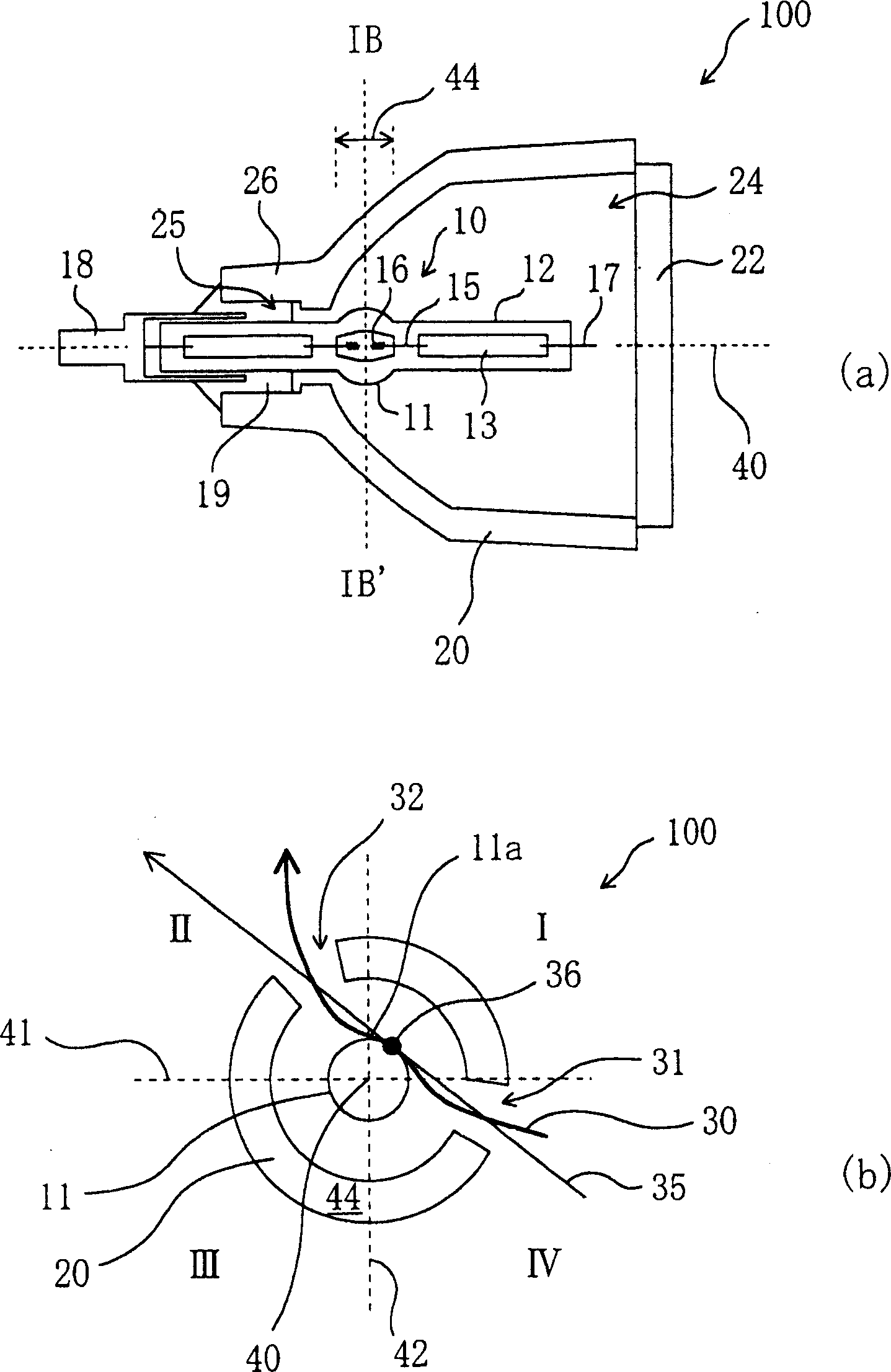
[0045] refer to figure 1 Embodiments of the present invention will be described. figure 1 (a) schematically shows the cross-sectional structure of the reflector-equipped lamp 100 of this embodiment; figure 1 (b) is along figure 1 A cross-sectional view taken along line IB-IB' in (a).

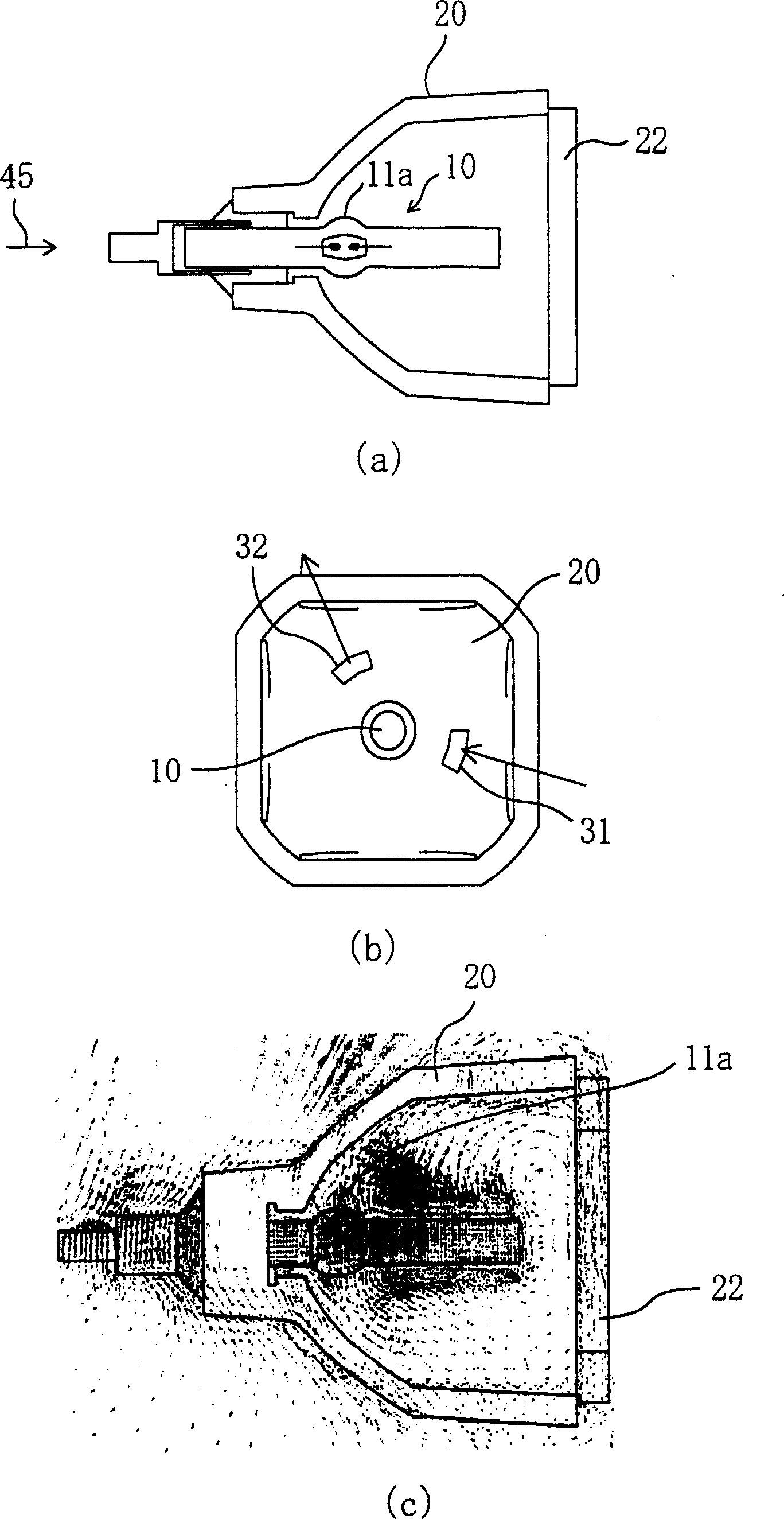
[0046] Such as figure 1 As shown in (a), the reflector-equipped lamp of this embodiment includes a high-pressure discharge lamp 10 and a reflector 20 that reflects light emitted from the high-pressure discharge lamp 10 . The high-pressure discharge lamp 10 has an arc tube 11 in which a luminescent substance is sealed, and a pair of sealing parts 12 extend substantially horizontally from both ends of the arc tube 11 .

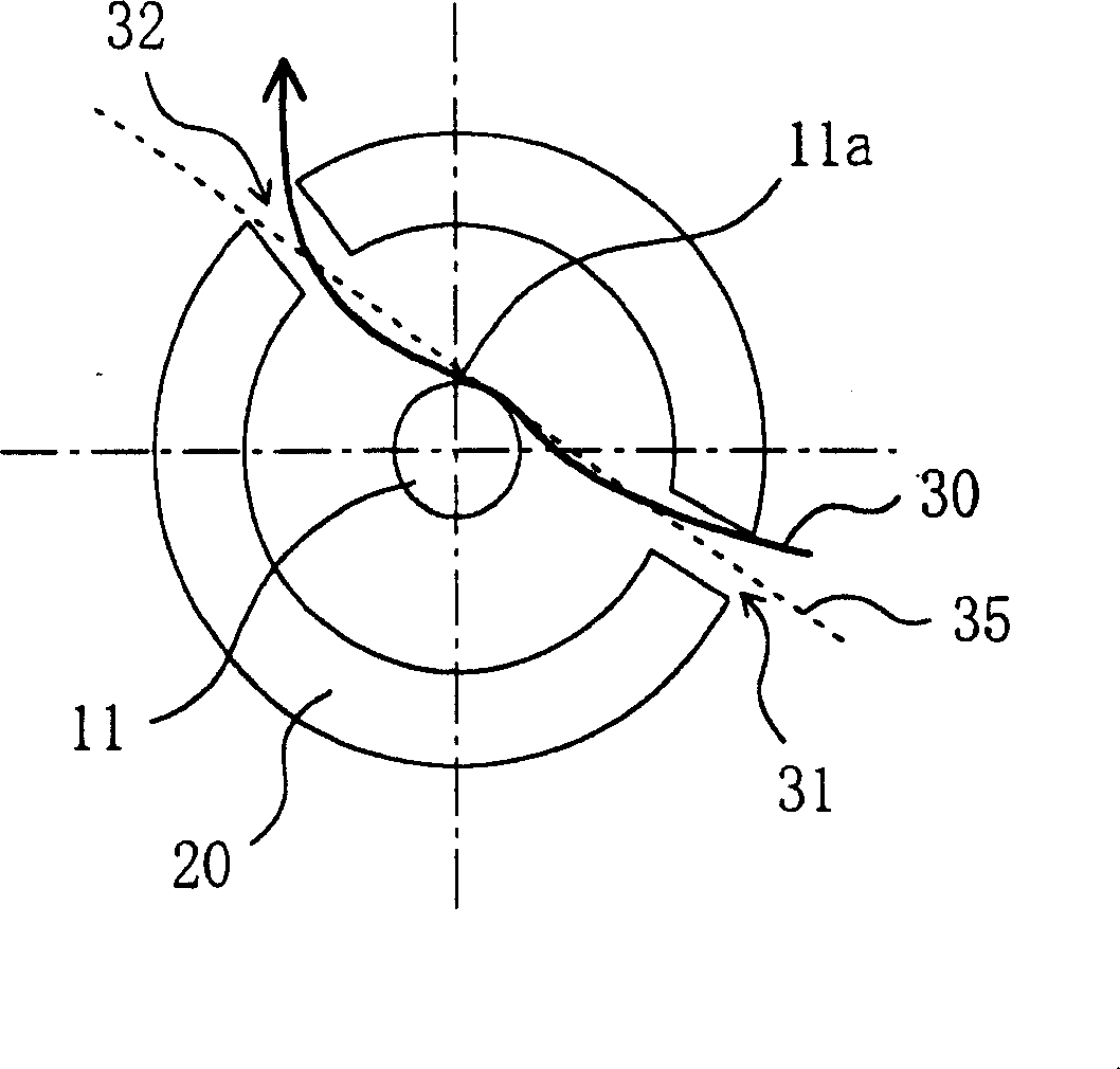
[0047] Such as figure 1 As shown in (b), two ventilation holes (31, 32) are formed on the reflecting mirror 20, and with respect to a substantially vertical line 42 passing through the center of the luminous tube 11, when viewed from the side of the wide opening 24 of t...


PUM


Abstract

A reflecting-mirror-equipped lamp 100 including a high pressure discharge lamp 10 and a reflecting mirror 20. An opening 24 of the reflecting mirror 20 is provided with a front glass 22 and two air holes (31 and 32) are formed through the reflecting mirror 20. The air holes (31 and 32) are provided on a cross section (44) including a luminous bulb 11. If the cross section 44 is divided into regions (I through IV) consisting of first, second, third and fourth quadrants with respect to the luminous bulb 11, the air holes (31 and 32) are respectively provided in two quadrants diagonal to each other, i.e., in the first and third quadrants, respectively, or in the second and fourth quadrants, respectively.

Description

technical field [0001] The invention relates to a lamp with a high-pressure discharge lamp and a reflector and an image projection device. In particular, it relates to a lamp with a reflector used as a light source of an image projection device such as a liquid crystal projector light source or a digital micromirror device (Digital Micromirror Device: DMD) projector. Background technique [0002] In recent years, image projection devices such as projectors using liquid crystal projectors and DMDs have been widely used as systems for realizing large-screen images. As a light source of such an image projection device, generally, a reflector-attached lamp composed of a high-intensity high-pressure discharge lamp combined with a reflector is widely used. [0003] In lamps with reflectors, in order to prevent heating during operation, most of them form air vents near the glass in front of the reflectors, and design cooling fans near the lamps with reflectors (for example, JP-A-2...

Claims


Application Information

Patent Timeline
IPC IPC(8): F21V7/00F21V29/83G03B21/20H01J5/16H01J61/34H01J61/52
Inventor 甲斐诚堀内诚高桥清畑冈真一郎关智行一番濑刚
Owner PANASONIC CORP
Why Eureka
Try Eureka