Apparatus and method for heating filament yarn

A heating device, filament technology, used in textiles and papermaking, etc.

Inactive Publication Date: 2004-06-23
SAURER GMBH & CO KG
View PDF3 Cites 4 Cited by
  • Summary
  • Abstract
  • Description
  • Claims
  • Application Information

AI Technical Summary

Problems solved by technology

This has the disadvantage that the finish vapors emanating from the filaments cause deposits directly in the heater, which are prevented by a continuously generated flushing air flow in the heating channel.
However, the problem cannot be solved in this w...

Method used


Image

  • Apparatus and method for heating filament yarn
  • Apparatus and method for heating filament yarn
  • Apparatus and method for heating filament yarn

Examples


Embodiment Construction

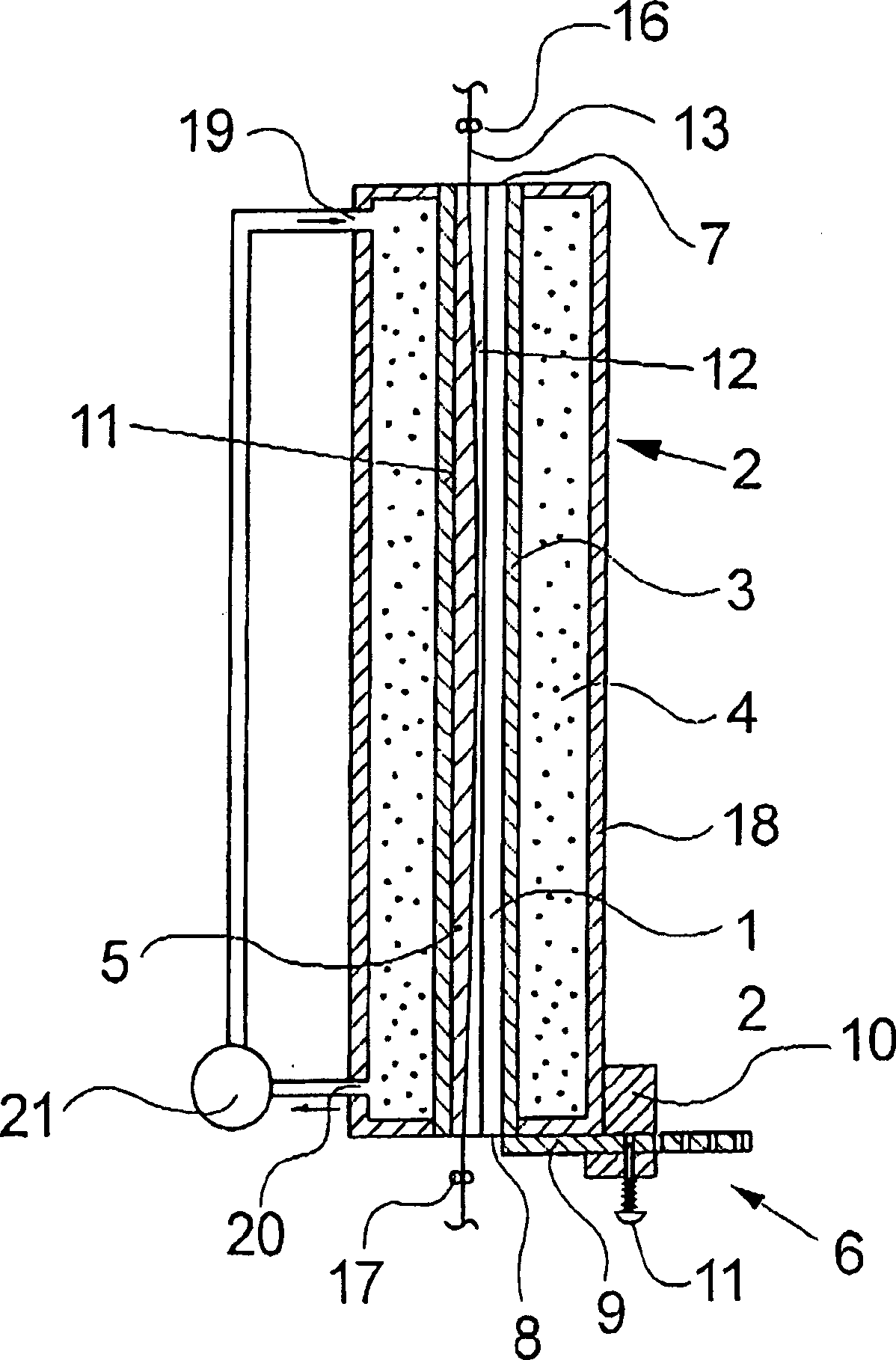
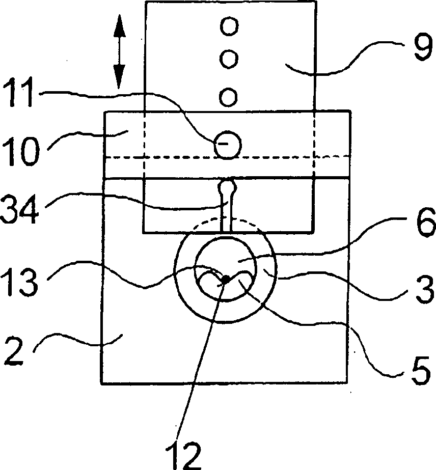
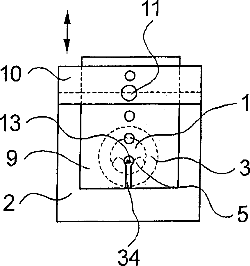
[0028] exist figure 1 shows schematically a longitudinal section through a first embodiment of a heating device according to the invention, which can be used, for example, in a texturing machine to heat texturized filaments for stress treatment in the shrinkage zone. FIG. 2 shows a front view of an exemplary embodiment of a heating device according to the invention. The following description applies to both figures unless specifically stated for one figure.

[0029] An exemplary embodiment of the heating device according to the invention has a long heating channel 1 with a wall 3 . In the present embodiment, the heating channel 1 with the wall 3 is formed by a thin-walled tube. The heating channel 1 is open at the end faces. An insert 5 is inserted into the heating channel 1 . The insert 5 has a longitudinal groove 12 in which the filaments 13 run in contact therewith. For this purpose, the longitudinal grooves 12 have a curvature on the groove base which is arranged in t...


PUM


Abstract

A control system (6, 15, 25, 28) is associated with the heating channel (1). Natural convection (chimney effect) through the channel, between its thread inlet (7) and outlet (8), is varied by the control system Control is applied by a tilting unit (15) varying the channel angle through 0degrees-90degrees with respect to a vertical initial position. Its bearing (22) and guide (23) are fitted to opposite ends of the channel. Variants based on the foregoing principles include a controlled cover flap, a controlled constriction and a variable additional air supply. The channel has insert(s) and is straight or curved. The heater is formed by a heating jacket (18) around the channel. This is connected to a vapor or steam source in a closed circuit. An Independent claim is included for the corresponding method of thread heating.

Description

technical field [0001] The invention relates to a heating device according to the preamble of claim 1 for heating filaments, in particular for the shrinkage treatment of texturized filaments, and a heating device for heating filaments according to the preamble of claim 13 method. Background technique [0002] During texturing of synthetic filaments, whether for texturing and stretching or for subsequent shrinkage, the filaments are heated by means of a heating device. Here, depending on the process steps, different heating devices have been developed, which allow the filaments to be heated optimally in the relevant process. In order to obtain a good stress relief effect on the filaments during the shrinking process, the filaments are as stress-free as possible. It is passed through a heating device in which the filament passes through an essentially vertically arranged heating channel, which is known, for example, from DE 343 527 A1. The heating channel here is preferably ...

Claims


Application Information

Patent Timeline
IPC IPC(8): D02J13/00
CPCD02J13/001
Inventor 马丁・菲舍尔
Owner SAURER GMBH & CO KG
Why Eureka
Try Eureka