
Rotary flow-crossover valve

A switching valve, rotary technology, applied in the field of rotary process switching valves, can solve problems such as damage to the simplicity and durability of valve components

Inactive Publication Date: 2004-06-30
SAGINOMIYA SEISAKUSHO INC
View PDF0 Cites 3 Cited by
  • Summary
  • Abstract
  • Description
  • Claims
  • Application Information

AI Technical Summary

Problems solved by technology

This compromises the smooth rotation of the valve element and the ease of operation for process exchange based on the rotation of the valve element
In addition, the main valve element and the spool suffer from abnormal deformation, so its durability is compromised

Method used


Image

  • Rotary flow-crossover valve
  • Rotary flow-crossover valve
  • Rotary flow-crossover valve

Examples


Embodiment Construction

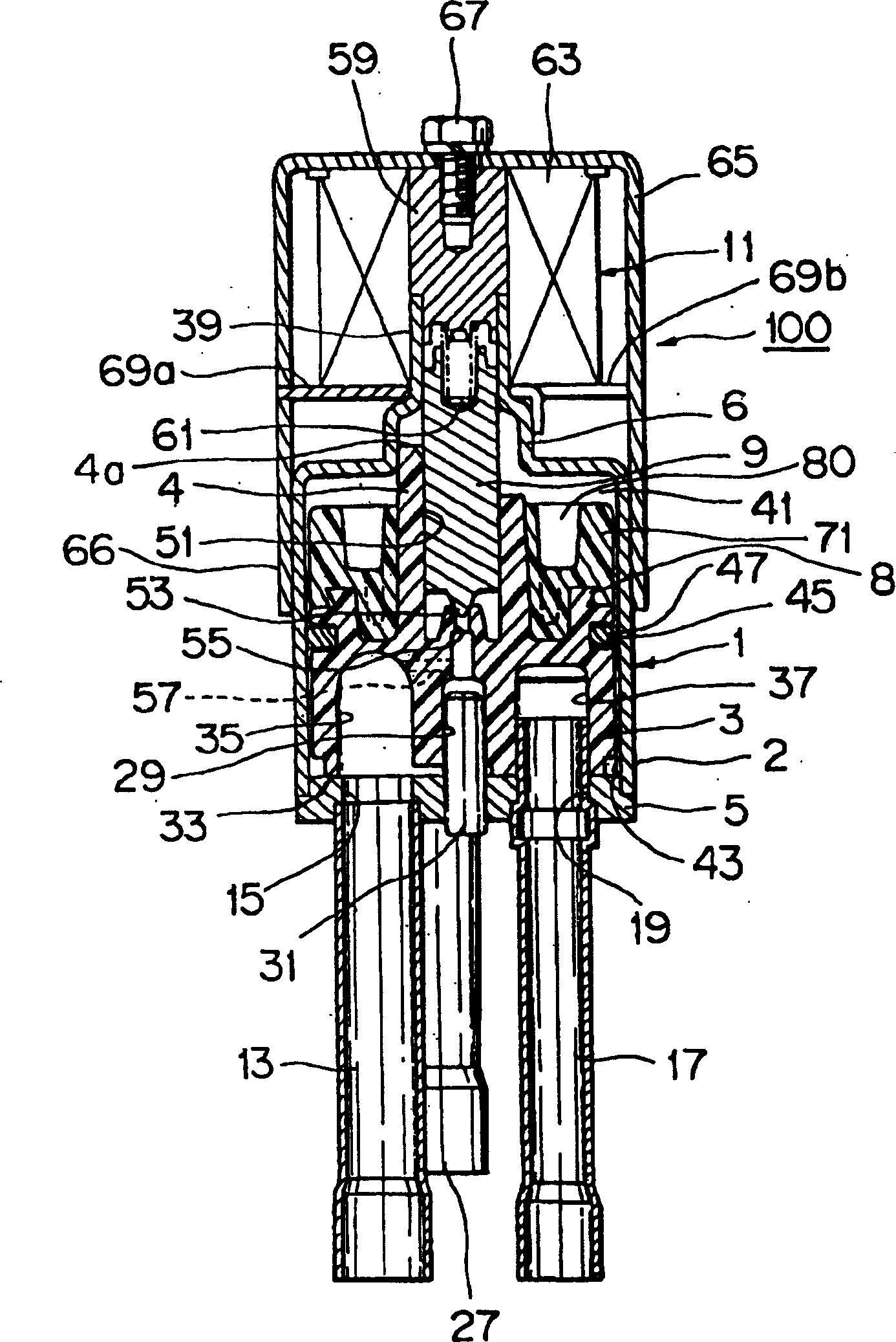
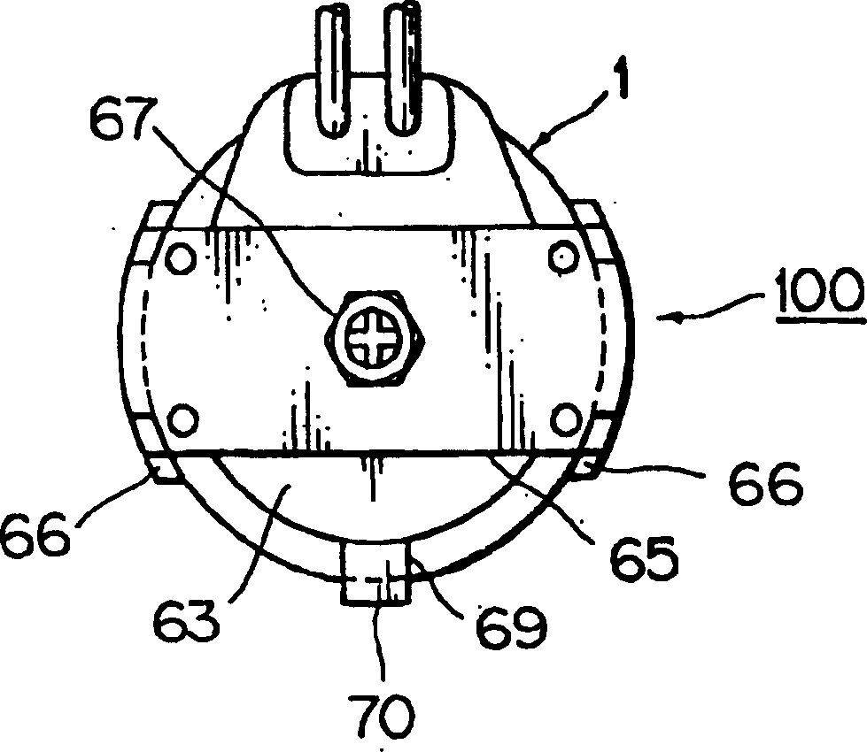
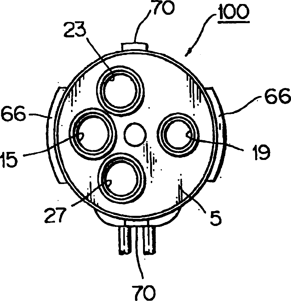
[0045] Reference now Figure 1 to 10 To explain the structure of the process exchange valve according to the embodiment of the present invention.

[0046] According to this embodiment, the rotary process exchange valve includes: a cylindrical valve housing 1, a main valve element 3 that can rotate and move in the direction of the rotation axis, a valve seat plate 5 fixed at the bottom of the valve housing 1, and a sliding The valve 9 and the solenoid 11 connected to the upper part of the valve housing 1.

[0047] As from Figure 5 As seen in 6, the structure of the rotary flow exchange valve is similar to the four-way valve 100 used in the steam pump system. In the position moved radially from its center, the valve seat plate 5 has: a low pressure port 15 with a low pressure pipe 13, which is connected from the suction side of the compressor P in the steam pump system; with a high pressure side The high pressure port 19 of the pipe 17, the pipe 17 is connected from the pressure re...


PUM


Abstract

In a rotary flow-path exchanging valve, the magnetic force generated in a pair of main magnetic pole pieces (66) by energization of an electromagnetic solenoid is acted on a multi-pole magnet (71) of a main valve element accommodated within a valve housing (1) so that the main valve element (3) is rotated to exchange a flow-path. The multi-pole magnet (71) is made of a plastic magnet of plastic material mixed with magnetic powder. The main valve element (3) and multi-pole magnet (71) are integrally formed by multiple molding. A pair of main magnetic pole pieces (66) magnetically connected to one polarity of the electromagnetic solenoid (11) are arranged. A pair of auxiliary magnetic pole pieces (70) connected to the other polarity of the electromagnetic solenoid (11) are arranged at positions out of phase from the magnetic pole pieces by 90 DEG . The pair of auxiliary magnetic poles (70) are opposed to portions of the multi-pole magnet (71) having a reverse polarity to that of portions of the multi-pole magnet (71) opposite to the main magnetic poles (66).

Description

Technical field [0001] The present invention relates to a process exchange valve, which is a three-way valve or a four-way valve and is used to exchange refrigeration processes in a steam pump type air conditioner, and in particular to exchange processes with the help of the rotary operation of valve elements Rotary process exchange valve. Background technique [0002] A typical example of the previously known rotary process exchange valve is the four-way valve disclosed in J-UM-7-16084 (pending review), which includes a cylindrical valve housing and a valve element that is rotationally coupled to the valve housing , Valve seat plate and electromagnetic actuator. The valve seat plate includes: a low pressure port fixed on the valve housing and connected with the low pressure pipeline, a high pressure port fixed on the high pressure pipeline, and at least one exchange port. [0003] The electromagnetic actuator includes: a multi-pole magnet connected to the valve element and arran...

Claims


Application Information

Patent Timeline
Patent Type & Authority Applications(China)
IPC IPC(8): F16K11/074F16K31/04F25B41/04
CPCY10T137/86839F16K31/041Y10T137/86863F25B41/046F16K11/0743
Inventor 杉田三男笠井宣中川升相原一登铃木和重平田和夫寺西敏博野田光昭大野道明金崎文雄
Owner SAGINOMIYA SEISAKUSHO INC
Learn More