Liquid injector and injecting method

A technology of jetting device and jetting direction, which is applied in the direction of inking device and printing, etc., which can solve the problems of image quality degradation and correction

Inactive Publication Date: 2004-07-07
SONY CORP
View PDF3 Cites 8 Cited by
  • Summary
  • Abstract
  • Description
  • Claims
  • Application Information

AI Technical Summary

Problems solved by technology

[0026] On the other hand, the line method configuration cannot be used as described above using the second method
Therefore, even in the case where a failure such as non-ejection occurs in a small amount of liquid ejection portion, the defect caused by the failure cannot be corrected, directly resulting in deterioration of image quality due to head failure.

Method used


Image

  • Liquid injector and injecting method
  • Liquid injector and injecting method
  • Liquid injector and injecting method

Examples


no. 1 example

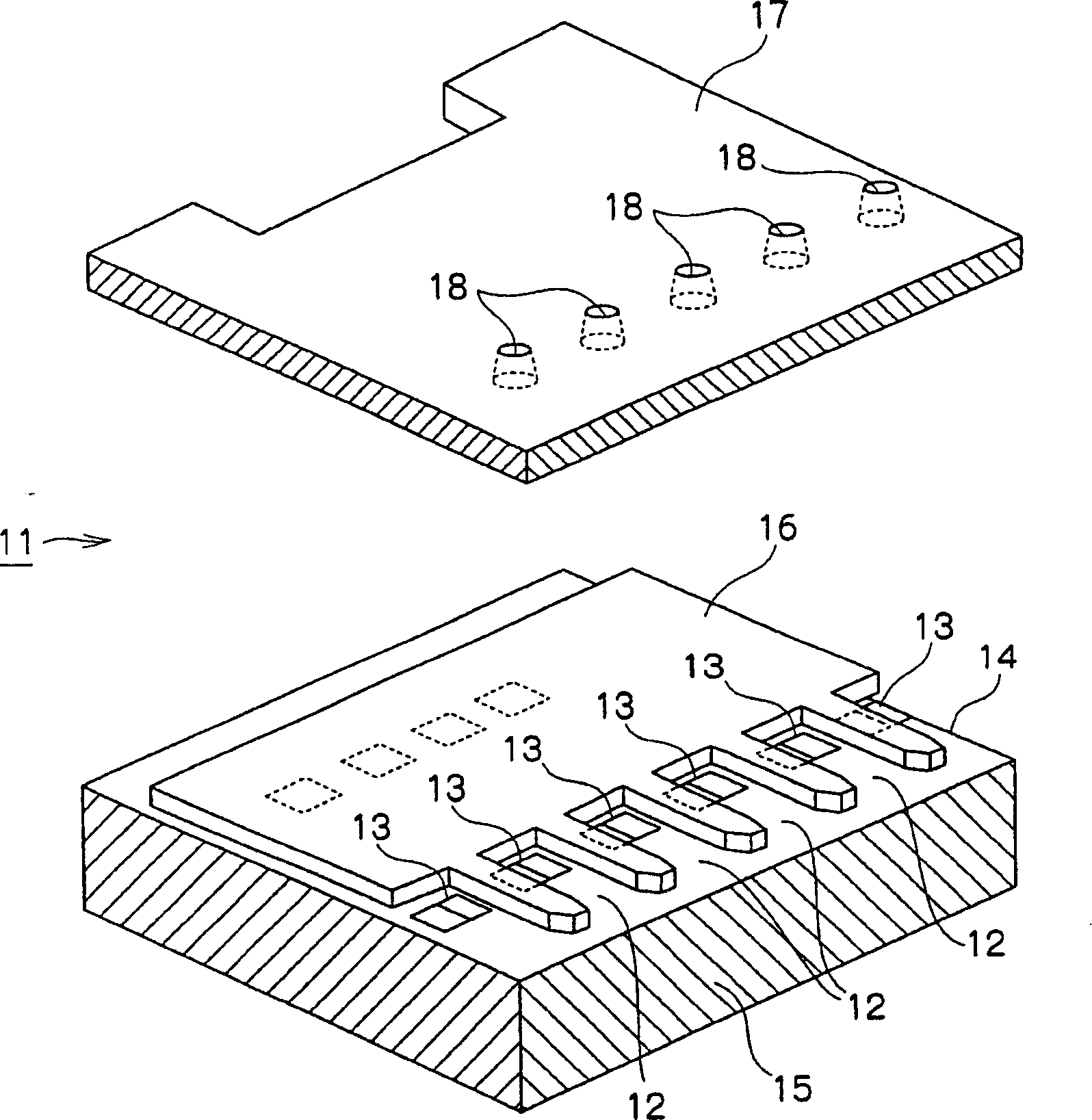
[0065] The first embodiment will be described with reference to the drawings and the like. Each embodiment is used to achieve the first object of the present invention. Note that the term "ink droplet" used here refers to a small amount (for example, several picoliters) of ink (liquid) ejected from one nozzle 18 of a liquid ejection section described later. Also, the term "dot" as used herein refers to a dot formed by ejecting one ink droplet onto a recording medium such as printing paper. Also, the term "pixel" as used herein refers to the smallest increment of an image, and the term "pixel area" as used herein refers to the area where a pixel is formed.

[0066] Usually, a predetermined number of droplets (0, 1 or more) are sprayed on each pixel area, so that pixels with a predetermined tone level (tone level 1, 2, 3, or more) are formed on each pixel area . That is, a pixel area has zero, one, or multiple dots corresponding to its tone level. In addition, a large number...


PUM


Abstract

The present invention discloses a liquid ejecting device that ejects a maximum of N liquid droplets so as to land on each pixel area to form a pixel corresponding to the pixel area, from among M liquid candidate drop positions that form an array along the nozzle arrangement direction Randomly select the target drop position of each droplet, determine the target drop position so that at least a part of the drop drop area corresponding to each candidate drop position is included in the pixel area, and control the ejection direction of the droplet so that the droplet falls at the determined target drop position. A liquid ejecting device having such a structure has an advantage of preventing streaks from being generated between dot matrixes of a printed image due to irregularities in the arrangement of the ejecting portions.

Description

technical field [0001] The present invention relates to a liquid ejecting device and a liquid ejecting method for ejecting liquid droplets, and more particularly, to a liquid ejecting device and a liquid ejecting method capable of providing improved image quality. Background technique [0002] In general, a conventional inkjet printer is a liquid ejecting device including a head in which ink ejecting portions each having a nozzle are arranged in a line. With this type of inkjet printer, a small liquid droplet (ink droplet) is ejected from each ink ejection portion of the head onto a recording medium such as printing paper set facing the end face of the nozzle to form a conventional circular dot on the recording medium , so that an image pixel is formed from a single point or multiple points. Also, the image pixels are two-dimensionally arranged to form images or characters. [0003] On the other hand, for an inkjet printer, liquid droplets with some irregularities are ejec...

Claims


Application Information

Patent Timeline
Patent Type & Authority Applications(China)
IPC IPC(8): B41J2/07B41J2/05B41J2/14B41J2/15B41J2/155B41J2/21
CPCB41J2/04573B41J2/155B41J2/04541B41J2/04578B41J2/0458B41J2/04581B41J2/04505B41J2/14056B41J2202/20B41J2/2132B41J2/15B41J2/04533B41J2/07
Inventor 江口武夫竹中一康牛滨五轮男池本雄一郎大关行弘
Owner SONY CORP
Why Eureka
Try Eureka