
Light emitting apparatus

a technology of light-emitting apparatus and discharge tube, which is applied in the direction of discharge tube/lamp details, discharge tube luminescnet screens, other domestic objects, etc., can solve the problems of insufficient value for color reproduction requirements, image reproduction cannot be highly accurate, and the lighting apparatus is difficult to achieve high-quality, uniform diffused effects

Active Publication Date: 2011-10-18
NICHIA CORP
View PDF23 Cites 6 Cited by
  • Summary
  • Abstract
  • Description
  • Claims
  • Application Information

AI Technical Summary

Benefits of technology

The solution enables a light emitting apparatus with improved color reproduction, reduced color unevenness, and increased brightness, lifespan, and cost-effectiveness by ensuring uniform phosphor distribution and adjustable color tones, suitable for large LCDs and other display applications.

Problems solved by technology

Accordingly, it is difficult for the lighting apparatus disclosed in Patent Document 1 to provide color reproduction region that accurately covers the entire range of the NTSC ratio.
As a result, there is a problem in that image reproduction cannot be highly accurately provided.
This value is not enough for the color reproduction requirement.
As for a white LED apparatus that has a combination of blue, red and green LEDs, although the white LED apparatus has an NTSC ratio of 100%, it is difficult to provide a white LED apparatus with long life at low cost.
However, since the phosphor in this light emitting apparatus greatly deteriorates, there is a problem in that the applicability of this light emitting apparatus is limited.
However, in the case the aforementioned phosphor is installed together with a light emitting device with a peak wavelength of 430 to 480 nm, the excitation wavelength for this phosphor does not agree with the peak wavelength of the light emitting device.
For this reason, the light emission efficiency of the phosphor is very poor.
In addition to this, even in the case where phosphors have ideal color reproduction and luminescent properties, if the phosphors are unevenly distributed in an installation area of a light emitting apparatus, the light emission amounts of different colors will be unevenly mixed.
This unevenness may cause color unevenness in the mixed light.
Consequently, it is difficult to provide LCDs with constant quality.
However, as for green luminescent type phosphors, a green luminescent type phosphor has not been developed that has excellent properties such as luminescent properties and durability, and has a variable peak wavelength while keeping these properties.

Method used


Image

  • Light emitting apparatus
  • Light emitting apparatus
  • Light emitting apparatus

Examples


first embodiment

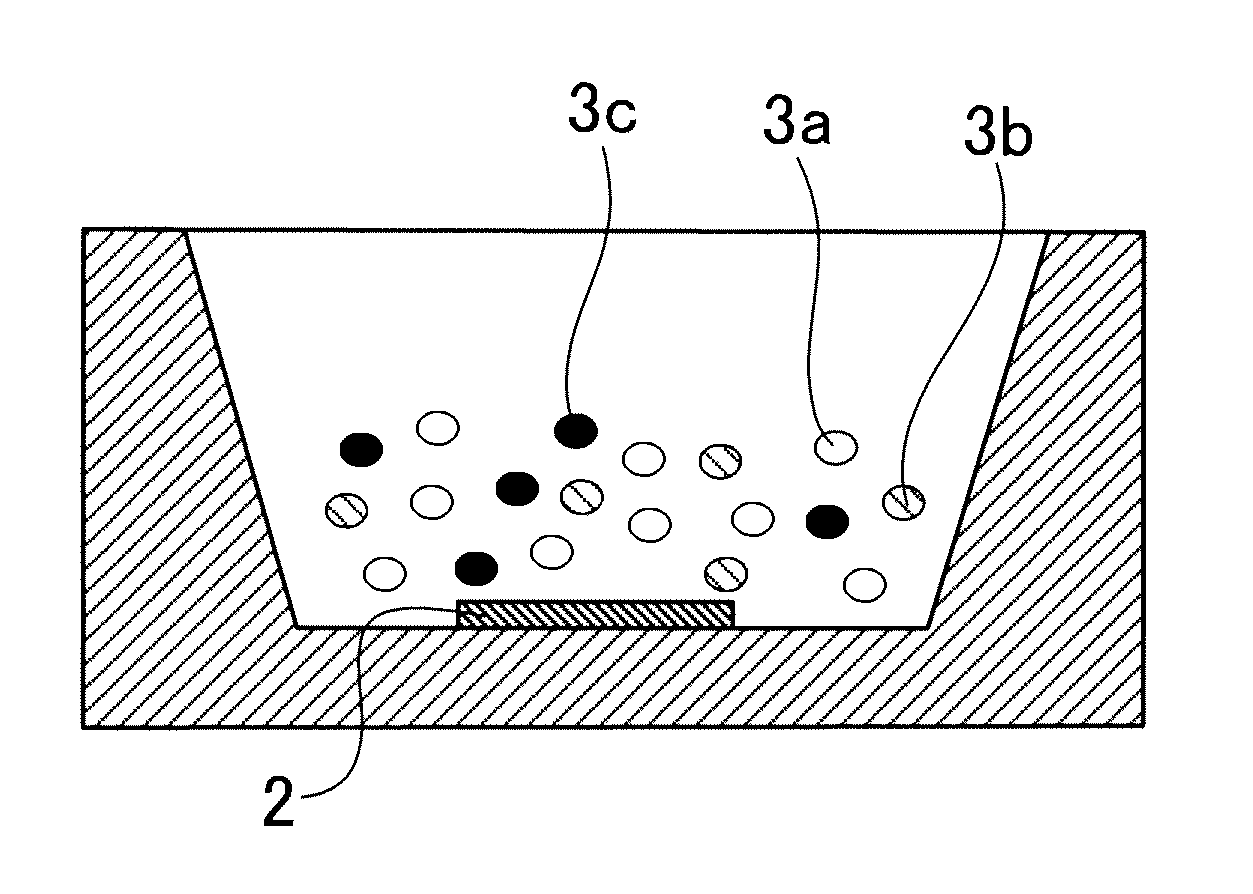
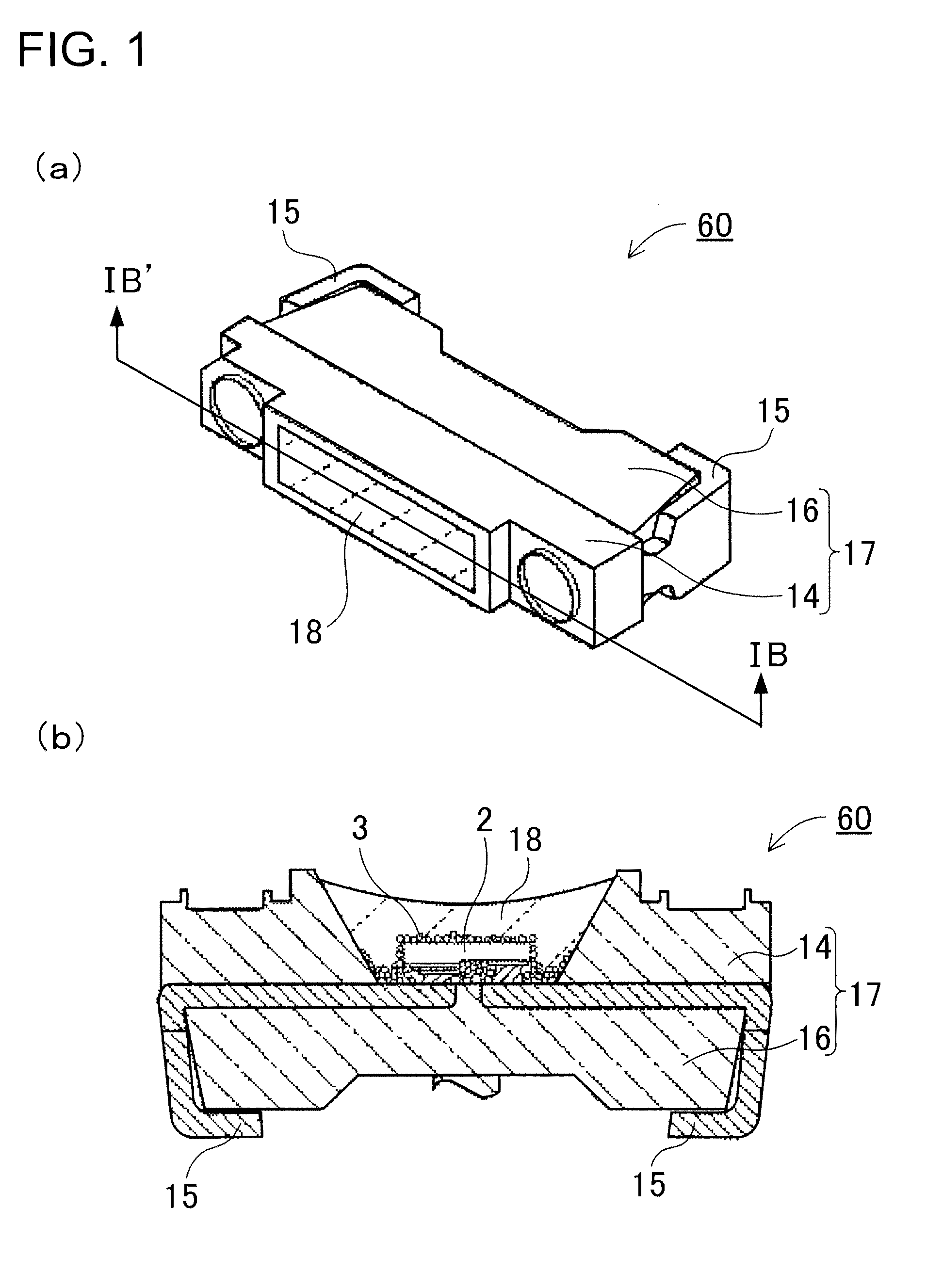
[0032]FIG. 1 shows a light emitting apparatus 60 according to a first embodiment of the present invention. FIG. 1(a) is a perspective view showing the light emitting apparatus 60. FIG. 1(b) is a cross-sectional view showing the light emitting apparatus 60 shown in FIG. 1(a) taken along the line IB-IB′. The illustrated light emitting apparatus 60 includes a light emitting device 2, and at least two types of phosphors 3, as shown in FIG. 1(b). The light emitting device 2 can emit light. The two or more types of phosphors 3 can be excited by the light emitted from the light emitting device 2 to emit light with wavelengths different from the wavelength of the light emitted from the light emitting device 2.

[0033]That is, the light emitting apparatus 60 includes a plurality of types of phosphors 3. The phosphors 3 according to the first embodiment 1 include a red luminescent type phosphor containing at least one type of nitride phosphor selected from the group consisting of phosphors of t...

example 1

[0102]Each light emitting apparatus according to an example 1 includes a blue luminescent type LED, and the following green luminescent type phosphor and the following red luminescent type phosphors. Specifically, a phosphor according to the example 1 is composed of one type of green luminescent phosphor, and two types of red luminescent phosphors mixed in the following weight ratio.[0103]Green: Si5.775Al0.21Eu0.015O0.023N7.910 [0104]Red: Ca1.94Si5N8:Eu0.06+Ca0.99AlSiB0.005N3.005:Eu0.01=2+8 in weight ratio

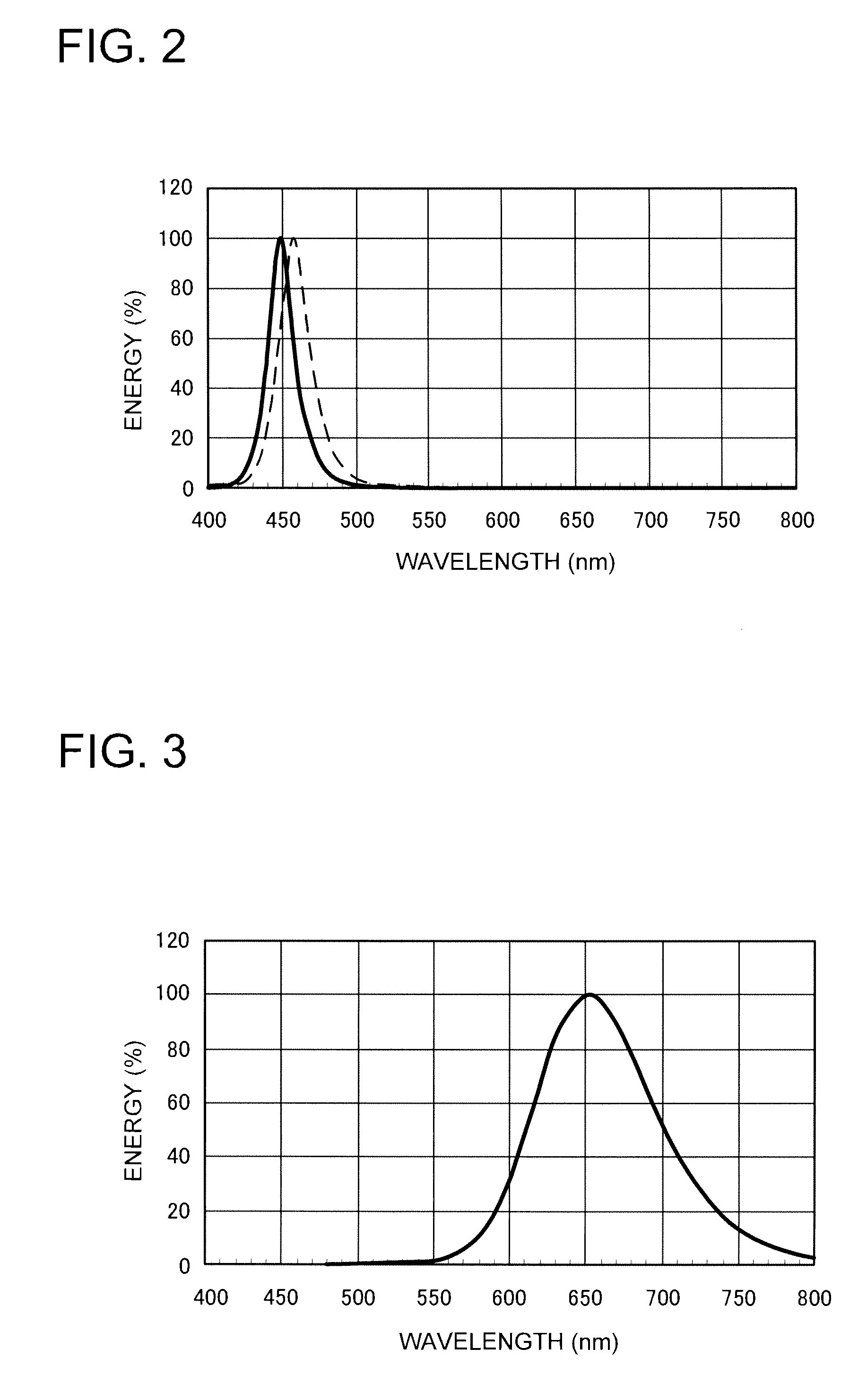
Two types of light emitting apparatuses are produced as type (a) and type (b) in each example by using blue luminescent LEDs having peak wavelengths of 450 and 460 nm. That is, the light emitting apparatus according to the example 1(a) includes an LED having a peak wavelength of 450 nm, and the light emitting apparatus according to the example 1(b) includes an LED having a peak wavelength of 460 nm. The following Table 3 shows conditions of LED peak wavelength, and the compositions...

example 2

[0108]The light emitting apparatuses according to examples 2 to 7 and the comparative example 1 have substantially the same configuration as the light emitting apparatus according to the example 1 except that the phosphor included in the light emitting apparatus according to the example 1 is substituted by phosphors shown below. Specifically, a phosphor according to the example 2 is composed of two types of green luminescent phosphors, and two types of red luminescent phosphors mixed in the following weight ratio.[0109]Green: Si5.775Al0.21Eu0.015O0.023N7.910+Ca7.5MgSi4O16Cl2-δ:Eu0.5=1+1 in weight ratio[0110]Red: Ca1.94Si5N8:Eu0.06 Ca0.99AlSiB0.005N3.005:Eu0.01=2+8 in weight ratio

Table 5 shows the compositions and the weight ratio of the phosphors, and the luminescent properties of the light emitting apparatus. FIG. 9 shows the light emission spectrum of an example 2(a) in LED 450 nm excitation. FIG. 10 shows the light emission spectrum of an example 2(b) in LED 460 nm excitation.

[01...


PUM

PropertyMeasurementUnit
peak wavelengthsaaaaaaaaaa
specific gravityaaaaaaaaaa

Abstract

A red nitride phosphor of formula (I) or (II), and two green phosphors of formulas (III) and / or (IV) are included.MwAlxSiyBzN((2 / 3)w+x+(4 / 3)y+z):Eu2+  (I)M is any of Mg, Ca, Sr and Ba, and 0.5≦w≦3, x=1, 0.5≦y≦3 and 0≦z≦0.5,MpSiqN((2 / 3)p+(4 / 3)q):EU2+  (II)1.5≦p≦2.5 and 4.5≦q≦5.5,MxMgSizOaXb:Eu2+  (III)M is any of Ca, Sr, Ba, Zn and Mn, X is any of F, Cl, Br and I, and 6.5≦x<8.0, 3.7≦z≦4.3, a=x+1+2z−b / 2 and 1.0≦b≦1.9,SicAldOfNg:Eu2+  (IV)c+d=6, 5.0≦c<6, 0<d≦1.0, 0.001<f≦1, 7≦g<8.

Description

TECHNICAL FIELD[0001]The present invention relates to a light emitting apparatus capable of emitting color reproduction improved light, and in particular relates to a light emitting apparatus having combination of a semiconductor light emitting device and phosphors.BACKGROUND ART[0002]Light emitting apparatuses have been developed that have a light emitting device, and a phosphor. The light emitting device emits source light. The phosphor is excited by the source light, and can emit light with a different color from the source light. Thus, the light emitting apparatuses can emit light with various wavelengths based on the additive color mixture principle. For example, in the case where a light emitting device emits primary light with a wavelength in a range of from ultraviolet to a short visible wavelength to excite RGB (Red, Green and Blue) phosphors as wavelength conversion members by using the emitted light, red, blue and green as three primary colors are additively mixed to prod...

Claims


Application Information

Patent Timeline
Patent Type & Authority Patents(United States)
IPC IPC(8): C09K11/08H05B33/00H01L33/00H01L33/50
CPCC09K11/0883C09K11/7734H01L33/504Y10S362/80Y10S428/917H01L2224/13H01L2224/48091H01L2224/8592H01L2224/48247H01L2224/49107H01L2224/73265H01L2924/00014H01L2224/05573H01L2224/05568H01L2924/181H01L2224/16245H01L2224/48257H01L2224/04042H01L2224/0554C09K11/77347C09K11/77348H01L2224/05599H01L2924/00012H01L2224/0555H01L2224/0556
Inventor HOSOKAWA, SHOJITAMAKI, HIROTO
Owner NICHIA CORP
Learn More