

Light emitting apparatus
a technology of light-emitting apparatus and discharge tube, which is applied in the direction of discharge tube/lamp details, discharge tube luminescnet screens, other domestic objects, etc., can solve the problems of insufficient value for color reproduction requirements, image reproduction cannot be highly accurate, and the lighting apparatus is difficult to achieve high-quality, uniform diffused effects
- Summary
- Abstract
- Description
- Claims
- Application Information
AI Technical Summary
Benefits of technology
Problems solved by technology
Method used
Image

Examples
first embodiment
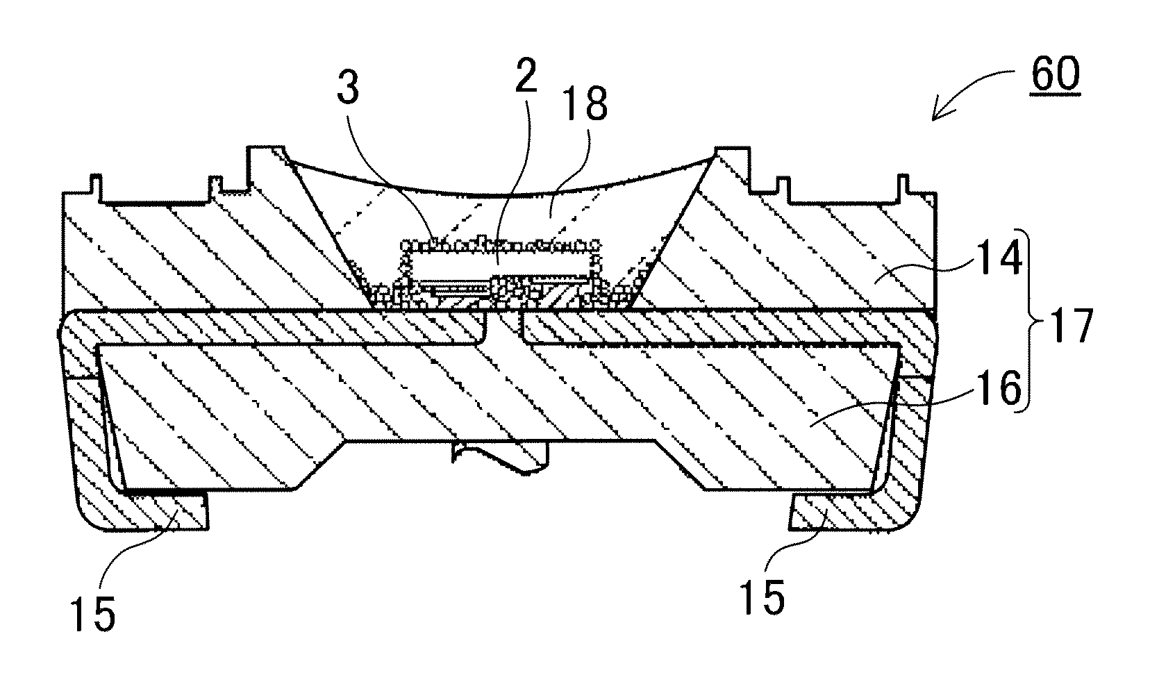
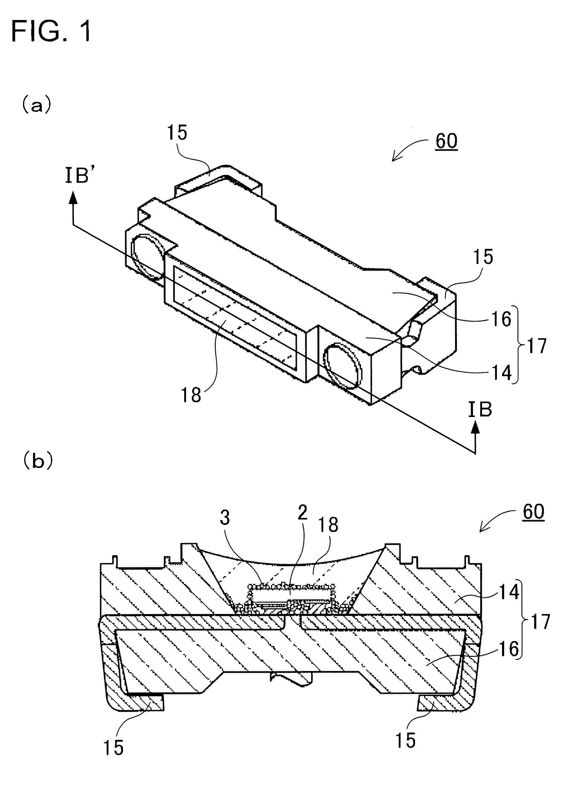
[0032]FIG. 1 shows a light emitting apparatus 60 according to a first embodiment of the present invention. FIG. 1(a) is a perspective view showing the light emitting apparatus 60. FIG. 1(b) is a cross-sectional view showing the light emitting apparatus 60 shown in FIG. 1(a) taken along the line IB-IB′. The illustrated light emitting apparatus 60 includes a light emitting device 2, and at least two types of phosphors 3, as shown in FIG. 1(b). The light emitting device 2 can emit light. The two or more types of phosphors 3 can be excited by the light emitted from the light emitting device 2 to emit light with wavelengths different from the wavelength of the light emitted from the light emitting device 2.
[0033]That is, the light emitting apparatus 60 includes a plurality of types of phosphors 3. The phosphors 3 according to the first embodiment 1 include a red luminescent type phosphor containing at least one type of nitride phosphor selected from the group consisting of phosphors of t...
example 1
[0101]Each light emitting apparatus according to an example 1 includes a blue luminescent type LED, and the following green luminescent type phosphor and the following red luminescent type phosphors. Specifically, a phosphor according to the example 1 is composed of one type of green luminescent phosphor, and two types of red luminescent phosphors mixed in the following weight ratio.[0102]Green: Si5.775Al0.21Eu0.015O0.023N7.910 [0103]Red: Ca1.94Si5N8:Eu0.06+Ca0.99AlSiB0.005N3.005:Eu0.01=2+8 in weight ratio
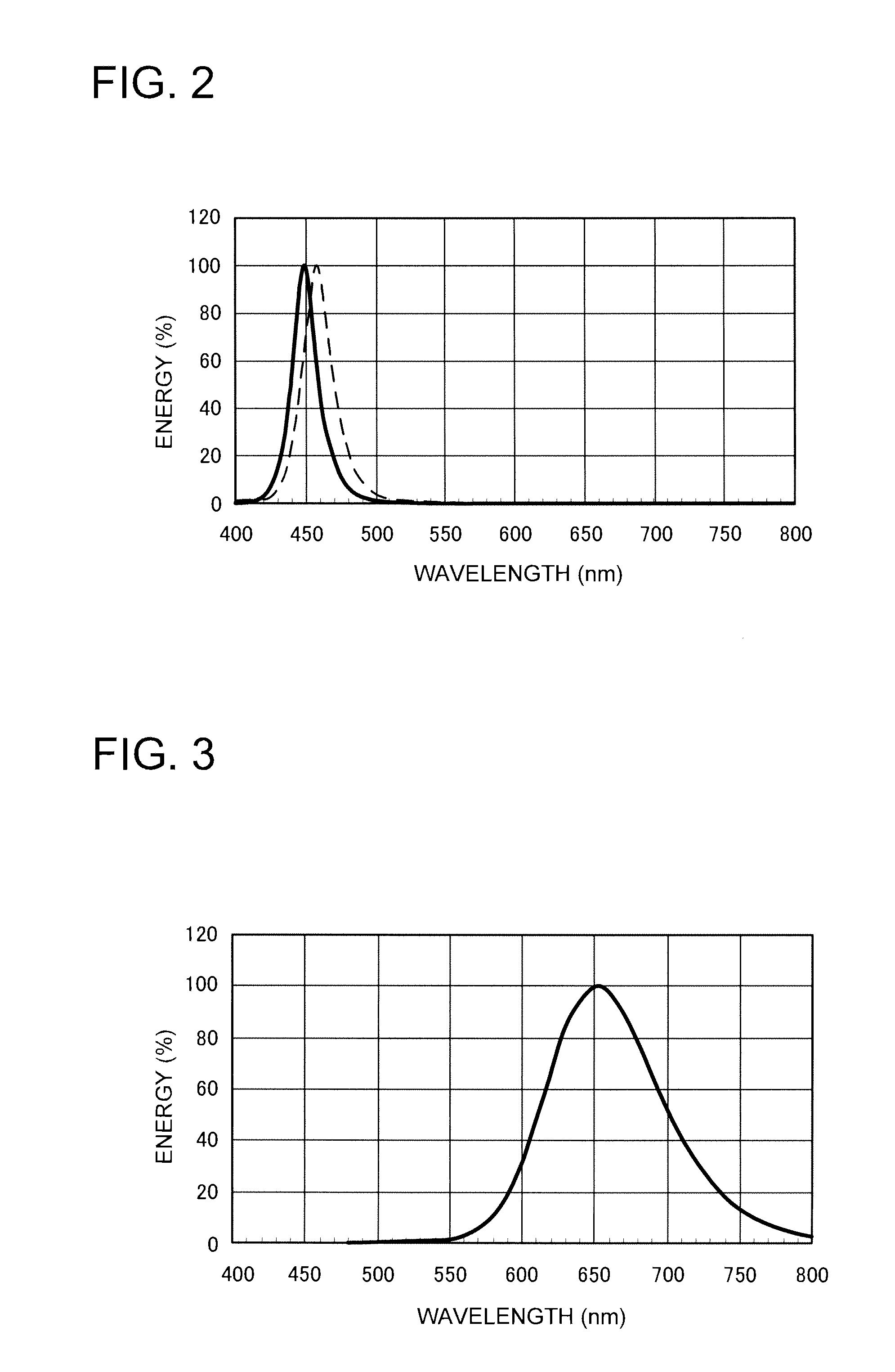
Two types of light emitting apparatuses are produced as type (a) and type (b) in each example by using blue luminescent LEDs having peak wavelengths of 450 and 460 nm. That is, the light emitting apparatus according to the example 1(a) includes an LED having a peak wavelength of 450 nm, and the light emitting apparatus according to the example 1(b) includes an LED having a peak wavelength of 460 nm. The following Table 3 shows conditions of LED peak wavelength, and the compositions...
example 2
[0105]The light emitting apparatuses according to examples 2 to 7 and the comparative example 1 have substantially the same configuration as the light emitting apparatus according to the example 1 except that the phosphor included in the light emitting apparatus according to the example 1 is substituted by phosphors shown below. Specifically, a phosphor according to the example 2 is composed of two types of green luminescent phosphors, and two types of red luminescent phosphors mixed in the following weight ratio.[0106]Green: Si5.775Al0.21Eu0.015O0.023N7.910+Ca7.5MgSi4O16Cl2-δ:Eu0.5=1+1 in weight ratio[0107]Red: Ca1.94Si5N8:Eu0.06 Ca0.99AlSiB0.005N3.005:Eu0.01=2+8 in weight ratio
Table 5 shows the compositions and the weight ratio of the phosphors, and the luminescent properties of the light emitting apparatus. FIG. 9 shows the light emission spectrum of an example 2(a) in LED 450 nm excitation. FIG. 10 shows the light emission spectrum of an example 2(b) in LED 460 nm excitation.
TAB...
PUM
 Abstract
Description
Claims
Application Information