
Structure For A High Efficiency And Water-Proof Lighting Device

a lighting device and high efficiency technology, applied in the field of fullcolor led lighting devices, can solve the problems of poor water resistance, energy consumption also becomes an important concern, and the seal between the light shade and the base holder can be broken, so as to achieve strong pull, enhance water-proof glue, and high water-proof

Inactive Publication Date: 2007-09-27
OPTO TECH
View PDF6 Cites 44 Cited by
  • Summary
  • Abstract
  • Description
  • Claims
  • Application Information

AI Technical Summary

Benefits of technology

[0006] The present invention has been made to overcome the above-mentioned drawback of conventional LED lighting device. The primary object of the present invention is to provide a water-proof LED lighting device. The main components of the lighting device are all separately enclosed objects so that the components will not interfere with each other when the components expand or shrink due to the temperature changes. Also, the electrical connection between the two components is glued with an enhanced water-proof glue that can stand strong pull. On one hand, the glue is soft as to absorb the deformation due the temperature changes. On the other hand, the glue provides water-proof connection. Therefore, the present invention is still highly water-proof in an environment that encompasses large temperature changes. In addition, the present design simplifies the structure so that the assembly of the components easier. With the multiple water-proof mechanisms, the lighting device of the present invention is highly water-proof.
[0007] Another object of the present invention is to provide a high efficiency LED lighting device. A highly-diffuse material, such as special acrylic, is used to enable the lights emitted from different LEDs are uniformly diffused. When observing from the outside, the present invention shows a uniformly mixed single color at a time. With the control of a computer program, the light color of the present invention can display the full range of colors to achieve the same visual effects of a neon-light. In addition, as a resilient element is used to connect the neighboring circuit substrate, the resilient element can absorb the deformation caused by the temperature changes so that the light diffusion remains uniform.
[0008] To achieve the above objects, the present invention provides a lighting device, including a light tube and a base holder. The light tube and the base holder are each an enclosed structure. The light tube includes a circuit substrate inside the enclosed structure. The circuit substrate includes a plurality of LEDs. The light tube and the base holder each include two holes close to both ends. When the light tube and the base holder are assembled, the holes match so that the wire connecting the circuit substrate can go through the holes to enter the base holder. A water-proof and highly pull-resistant glue is used to fill the overlapping of the holes. When the light tube and the base holder expand or shrink differently due to the temperature changes, the glue will absorb the discrepancy of the deformation to sustain the structure.

Problems solved by technology

However, as the energy resource is becoming scarce, the energy consumption also becomes an important concern when using lights.
The water resistance is poor in an environment where the temperature experiences significant changes.
As a result, the tight seal between the light shade and the base holder can be broken and leads to water leakage.
The manufacturing process is complicated and time-consuming.
As a result, the yield rate is poor if addition caution is not taken during the sealing process.

Method used


Image

  • Structure For A High Efficiency And Water-Proof Lighting Device
  • Structure For A High Efficiency And Water-Proof Lighting Device
  • Structure For A High Efficiency And Water-Proof Lighting Device

Examples


Embodiment Construction

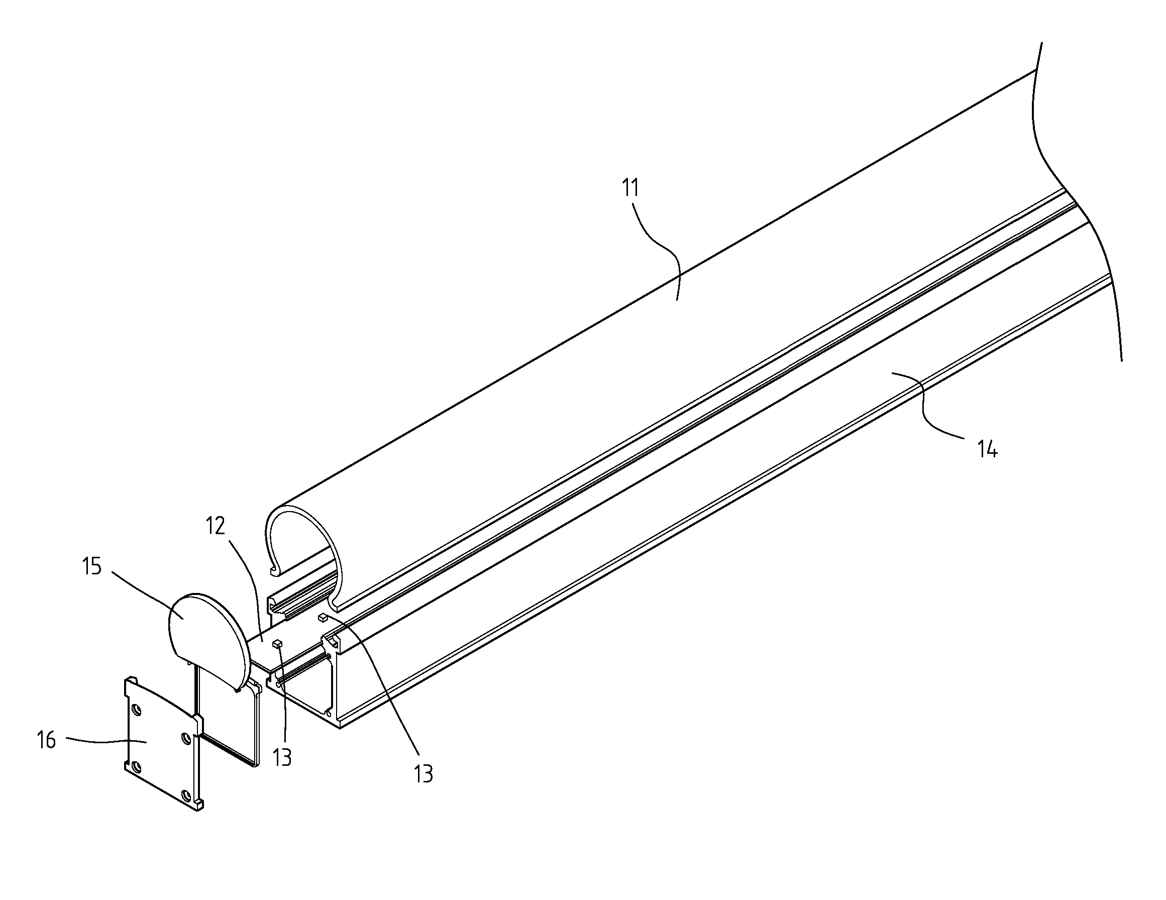
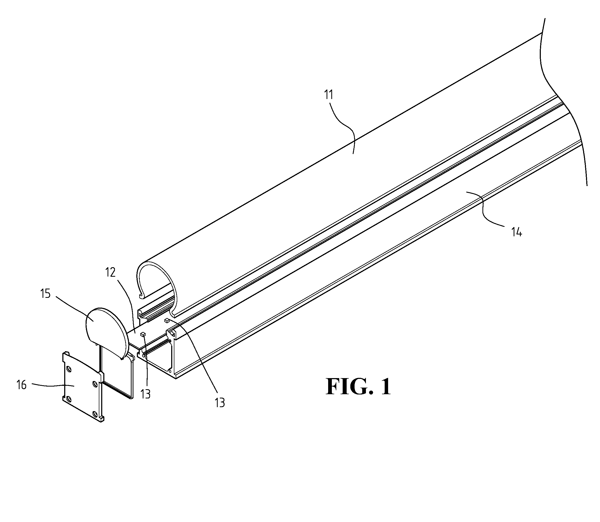
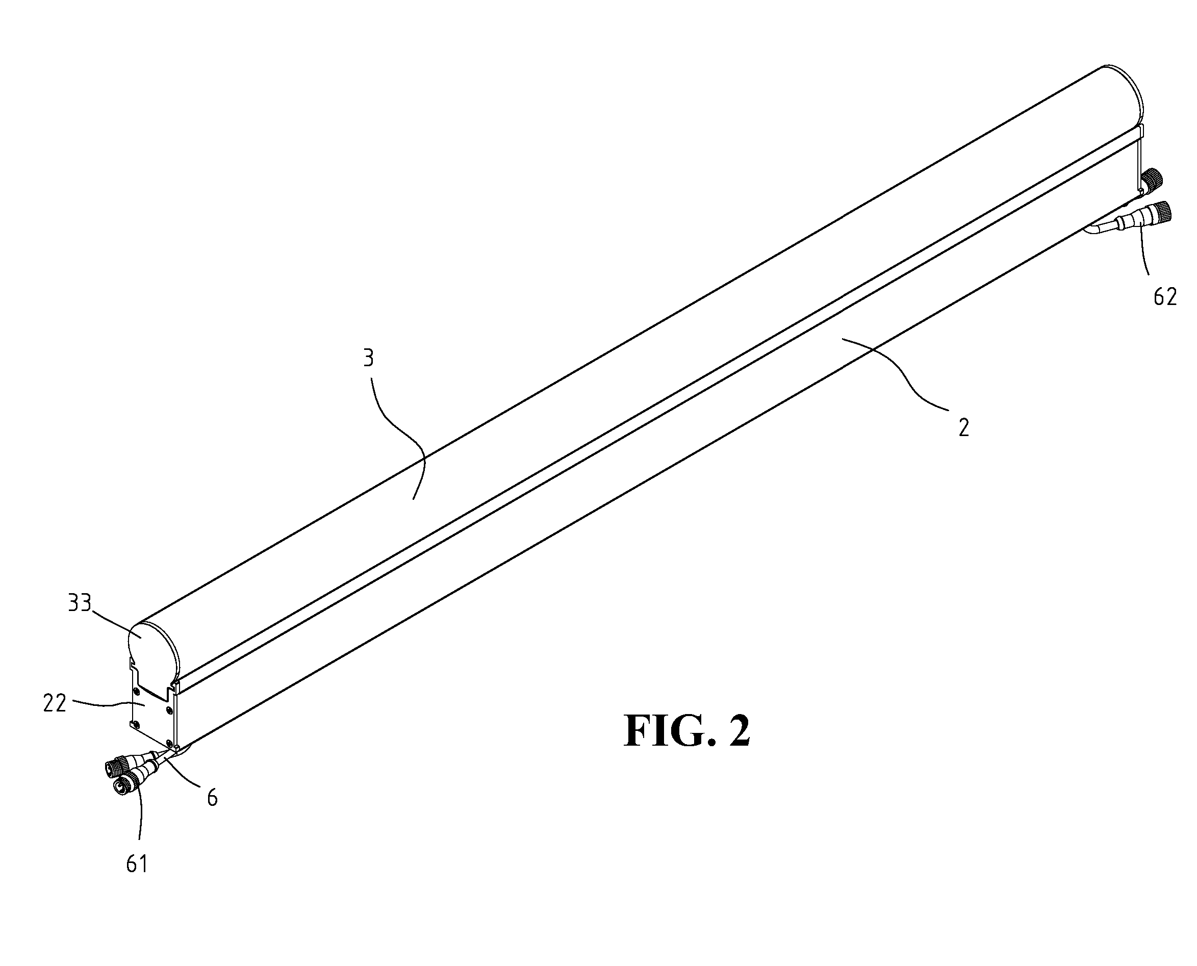
[0011]FIGS. 2 & 3 show the three-dimensional and exploded view of the present invention. The present invention includes a base holder 2 and a light tube 3. Light tube 3 is engaged to base holder 2 from the top. Light tube 3 includes at least a circuit substrate 4. Circuit substrate 4 is enclosed inside light tube 3. Each circuit substrate 4 includes a plurality of LED units 41. Each LED unit 41 includes one or more red, green, and blue LEDs, so that each LED unit 41 can provide full color light.

[0012] As shown in FIG. 3, a guiding trench 31 is included inside light tube 3. Guiding trench 31 is located on the facing side walls of light tube 3. Circuit substrate 4 is inserted to guiding trench 31 so that the vertical location of circuit substrate 4 is fixed.

[0013]FIG. 4 shows another embodiment of a plurality of circuit substrates 4 when light tube 3 is sufficient longer to accommodate more circuit substrates 4. A resilient arc element 5 is used to connect two neighboring circuit su...


PUM


Abstract

A structure for a high diffuse efficiency and water-proof lighting device is provided, including a light tube and a base holder. The light tube and the base holder are each an enclosed structure. The light tube includes a circuit substrate inside the enclosed structure. The circuit substrate includes a plurality of LEDs. The light tube and the base holder each include two holes close to both ends. When the light tube and the base holder are assembled, the holes match so that the wire connecting the circuit substrate can go through the holes to enter the base holder. A water-proof and highly pull-resistant glue is used to fill the overlapping of the holes. A resilient element is used to connect the neighboring circuit substrates, the resilient element can absorb the deformation caused by the temperature changes so that the light diffusion remains uniform. Therefore, the lighting device can perform well even when operating in an environment with drastic temperature changes.

Description

FIELD OF THE INVENTION [0001] The present invention generally relates to a full-color LED lighting device, and more specifically to a high efficiency and water-proof structure of a full-color LED lighting device. BACKGROUND OF THE INVENTION [0002] As the modern demands in living environment, the lighting is playing an even more important role than ever. Nowadays, the lights are no longer for illuminations for people to see in the dark, lights are also used in creating certain atmosphere and are becoming part of an architecture or art design. However, as the energy resource is becoming scarce, the energy consumption also becomes an important concern when using lights. The recent development of LED has brought about the revolutionary changes in the lighting devices. The LED lighting devices can be directly controlled by a computer program for changing the color, the intensity and the ON / OFF interval to display full color ranges. This is more visually appealing than the conventional ne...

Claims


Application Information

Patent Timeline
IPC IPC(8): F21V9/00
CPCF21S4/008F21S8/031F21V15/01F21V15/015F21Y2103/003F21V23/02F21V27/02F21V31/005F21Y2101/02F21V19/0045F21S4/28F21Y2103/10F21Y2115/10
Inventor YOU, JU-YUANYEH, CHIEN-LIANGLEE, ZONG-HUAICHANG, CHIEN-FENGLIN, CHAN-PENG
Owner OPTO TECH
Learn More