Magnetic sensor

A magnetic detection and magnetic field technology, which is applied to magnetic recording heads, the magnitude/direction of magnetic fields, and the manufacture of magnetic flux-sensitive magnetic heads, etc., can solve the problems of difficult to improve compensation accuracy, increased cost, and inability to correct output drift effects

Inactive Publication Date: 2004-07-14
FUJI ELECTRIC FA COMPONENTS & SYST CO LTD
View PDF4 Cites 18 Cited by
  • Summary
  • Abstract
  • Description
  • Claims
  • Application Information

AI Technical Summary

Problems solved by technology

[0009] However, when using Figure 16 In the method shown, since only the variable resistor VR can be used to adjust the variable sensitivity of the magnetoresistive element 1, it is extremely difficult to minimize the deviation of the sensitivity
In addition, in order to minimize the sensitivity deviation of the magnetoresistive element 1 by using the above-mentioned detection circuit, it is necessary to adjust and correct each detection circuit, thus greatly increasing the cost
Although the detection circuit can be properly adjusted and corrected, this problem makes it difficult to improve the compensation accuracy because the output drift effect caused by the quality degradation of the detection circuit over time cannot be corrected

Method used


Image

  • Magnetic sensor
  • Magnetic sensor
  • Magnetic sensor

Examples


Embodiment Construction

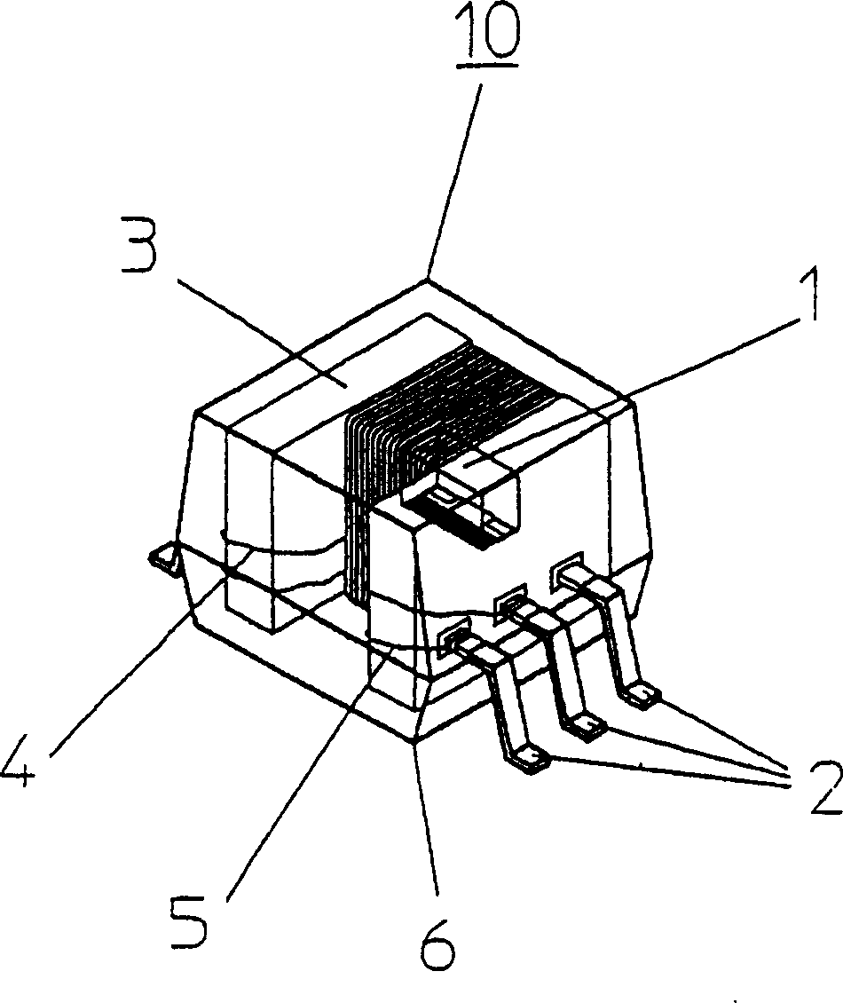
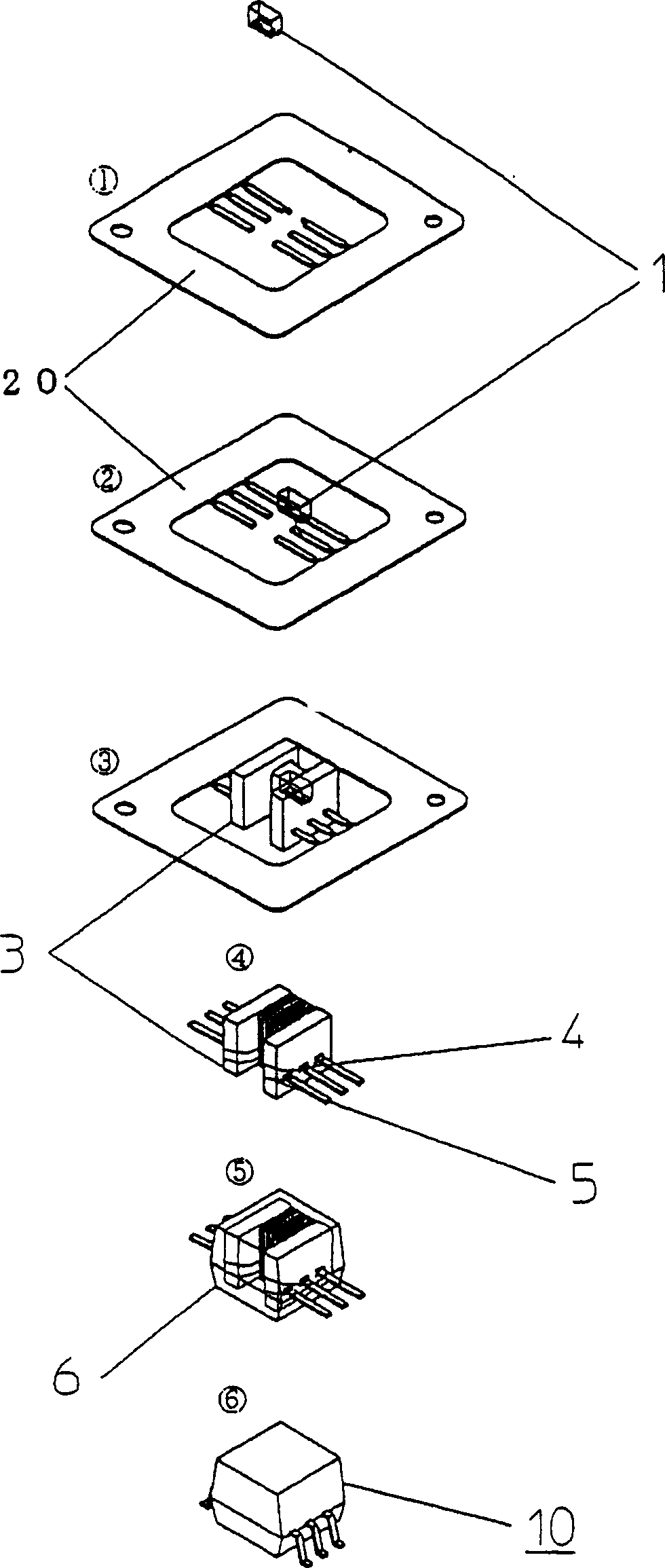
[0034] figure 1 It is an exploded perspective view of the magnetic detection device embodying the first embodiment of the present invention. Reference numeral 1 denotes a magnetoresistive element having a thin film configuration. Reference numeral 3 denotes a resin bobbin formed on the outer side of the magnetoresistive element 1 by an insert-molding process. Reference numeral 4 denotes a coil for applying a bias magnetic field to the magnetoresistive element 1. Reference numeral 5 denotes a coil for applying a negative feedback magnetic field to the magnetoresistive element 1. Reference numeral 6 denotes a resin case for protecting the magnetoresistive element 1 and the coils 4 and 5 from various environments, wherein the resin case 6 is formed by an insert molding process. Reference numeral 2 denotes a terminal for applying a high-frequency current to both ends of the magnetoresistive element 1 and also for applying a current to the coils 4 and 5. Reference numeral 10 denotes ...


PUM


Abstract

Provided is a magnetism detection apparatus that is small and low in cost and power consumption, a biasing coil 4 and a negative-feedback coil are integrated with a magnetic impedance element having a magnetic impedance effect in a resinous structure. The magnetism detection apparatus has a reduced magnetic resistance between the magnetic impedance element and the coil, thereby making it possible to apply a bias magnetic field and a negative-feedback magnetic field to the magnetic impedance element with a reduced power consumption.

Description

Technical field [0001] The present invention relates to a magnetic detection device using the magnetoresistance effect, and more particularly, to a magnetic detection device with an improved structure. Background technique [0002] In the past, Hall elements or magnetoresistive elements have been widely used in magnetic detection devices. However, only a few of these components can achieve satisfactory magnetic detection sensitivity. Therefore, various solutions have been proposed for replacing the traditional magnetoresistive element with a high-sensitivity magnetic detection element. These solutions include magnetoresistive elements based on amorphous wire applications as disclosed in Japanese Patent Laid-Open No. 6-281712 (1994) and thin-film applications as disclosed in Japanese Patent Laid-Open No. 8-075835 (1996)的magnetoresistive element. [0003] Although any magnetoresistive element of any shape exhibits its own magnetic detection characteristics with high sensitivity, th...

Claims


Application Information

Patent Timeline
Patent Type & Authority Applications(China)
IPC IPC(8): G01R33/02G11B5/33H01L43/00
CPCG01R33/02G01R15/14
Inventor 工藤隆裕北出雄二郎
Owner FUJI ELECTRIC FA COMPONENTS & SYST CO LTD
Why Eureka
Try Eureka