
Hydraulic circuit for crane

A hydraulic circuit, crane technology, applied in cranes, mechanical equipment, servo meter circuits, etc., can solve problems such as increasing costs

Inactive Publication Date: 2004-07-28
KOBELCO CRANE
View PDF0 Cites 1 Cited by
  • Summary
  • Abstract
  • Description
  • Claims
  • Application Information

AI Technical Summary

Problems solved by technology

The problem in this case is that the additional installation of the hydraulic source 17 will increase the cost, installation space and pipes, etc.

Method used


Image

  • Hydraulic circuit for crane
  • Hydraulic circuit for crane
  • Hydraulic circuit for crane

Examples


Embodiment Construction

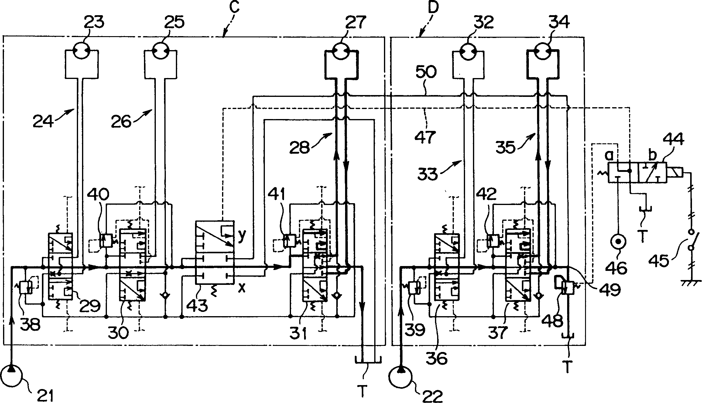
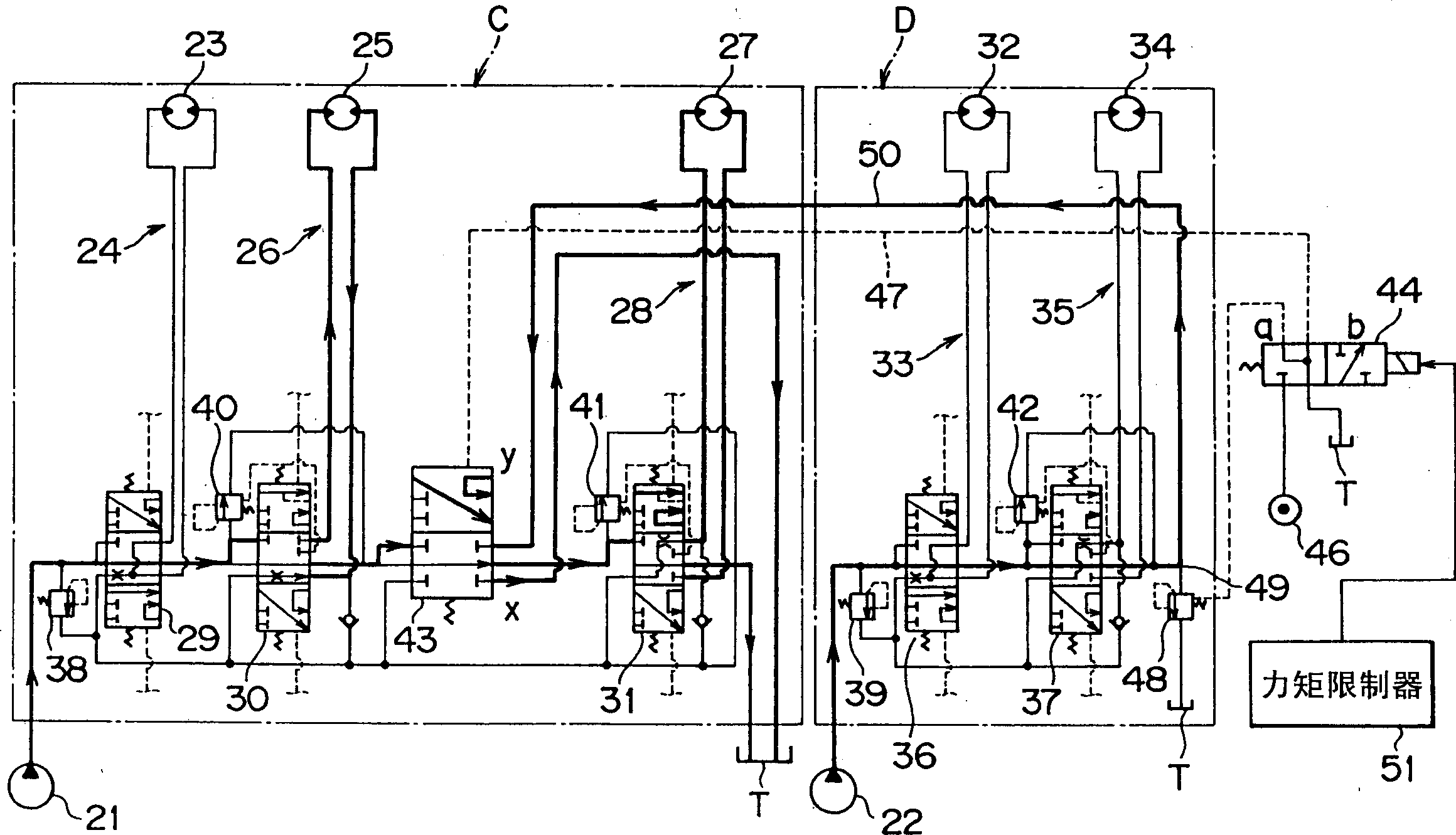
[0027] Refer below figure 1 and figure 2 Several preferred embodiments of the present invention are described. This is just one example of the present invention, and the present invention is not limited to this example.

[0028] exist figure 1 and figure 2 Among them, C represents the first actuator group with the first hydraulic source 21 , and D represents the second actuator group with the second hydraulic source 22 .

[0029] The first actuator group C includes a left travel motor circuit 24 driving a left travel motor 23 , a hanger raising motor circuit 26 driving a hanger raising and lowering motor 25 , and an auxiliary motor circuit 28 driving an auxiliary winch motor 27 . The motor circuits 24 , 26 and 28 are connected in series between the hydraulic pressure source 21 and the oil tank T through mutual control valves 29 , 30 and 31 .

[0030] The second actuator group D includes a right travel motor circuit 33 driving a right travel motor 32 and a main motor c...


PUM


Abstract

The present invention provides a hydraulic circuit for a crane wherein a switching valve is provided between a plurality of motor circuits connected in series within the same actuator group, and at the time of simultaneous operation of the motor circuits, the switching valve is switched from a first position to a second position whereby the series connection between the motor circuits is cut off, and they are driven by each of separate hydraulic sources, thereby enabling prevention of pressure interference at the time of simultaneous operation of the motor circuits within the same actuator group without increasing hydraulic sources.

Description

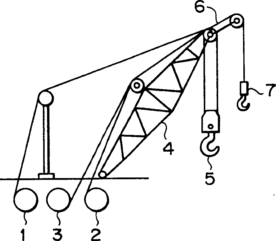
technical field [0001] The present invention relates to a hydraulic circuit for a crane, wherein a hanger hoist motor circuit and a winch motor circuit are connected in series with a hydraulic source. Background technique [0002] Ordinary crawler cranes are provided with winches 1, 2 and 3, which are hanger hoisting winches, main winches and auxiliary winches, such as image 3 shown. The main boom (hanger) 4 is lifted by the hanger lifting winch 1 . The main hook 5 suspended at the end of the main jib 4 is raised and lowered by the main winch 2 . The auxiliary hook 7 is suspended on the auxiliary boom 6 and is raised and lowered by the auxiliary winch 3, and the auxiliary boom 6 is fixed at the end of the main boom. [0003] In a horizontal crane, the auxiliary jib 9 is fixed at the end of the main tower jib 8, such as Figure 4 shown. The main hook 5 is suspended at the end of the auxiliary jib 9 . The auxiliary boom 9 is lifted by the auxiliary winch 3 . [0004] Op...

Claims


Application Information

Patent Timeline
Patent Type & Authority Applications(China)
IPC IPC(8): B66C13/20B66C13/18B66C23/00B66C23/82E02F9/22F15B11/17
CPCF15B2211/30595F15B2211/329F15B2211/20576E02F9/2292F15B2211/3116F15B2211/57F15B2211/55F15B2211/50518F15B2211/7058B66C13/18F15B2211/50563F15B2211/78F15B11/17F15B2211/351
Inventor 江原正明山县克己小林隆博角尾泰辅山本良伊藤登
Owner KOBELCO CRANE
Learn More