Broadband dispersion controlled optical fibre

An optical fiber and dispersion technology, applied in clad optical fibers, multi-layer core/clad optical fibers, optics, etc., can solve the problems of increasing the construction cost of optical communication networks and reducing the efficiency of Raman amplification

Inactive Publication Date: 2004-08-04
SAMSUNG ELECTRONICS CO LTD
View PDF0 Cites 1 Cited by
  • Summary
  • Abstract
  • Description
  • Claims
  • Application Information

AI Technical Summary

Problems solved by technology

However, since such large effective area fibers have considerable dispersion values ​​in the L-band wavelength range, it is necessary to compensate for the dispersion
In addition, there is a problem that if the effective cross-sectional area increases, the Raman amplification efficiency will decrease
Therefore, due to the use of different types of optical fibers according to the transmission wavelength, the construction cost of the optical communication network is doubled

Method used


Image

  • Broadband dispersion controlled optical fibre
  • Broadband dispersion controlled optical fibre
  • Broadband dispersion controlled optical fibre

Examples


Embodiment Construction

[0027] In the following description of the present invention, for purposes of explanation rather than limitation, specific details are set forth such as specific structures, interfaces, techniques, etc. in order to provide a thorough understanding of the present invention. It will be apparent, however, to one skilled in the art that the present invention may be practiced in other embodiments that depart from these specific details. Also, it will be appreciated that certain aspects of the drawings have been simplified for purposes of explanation and that the overall system environment of the invention will include many known functions and configurations that need not be fully shown here. In the drawings, the same or similar elements are denoted by the same reference symbols even if they are shown in different drawings.

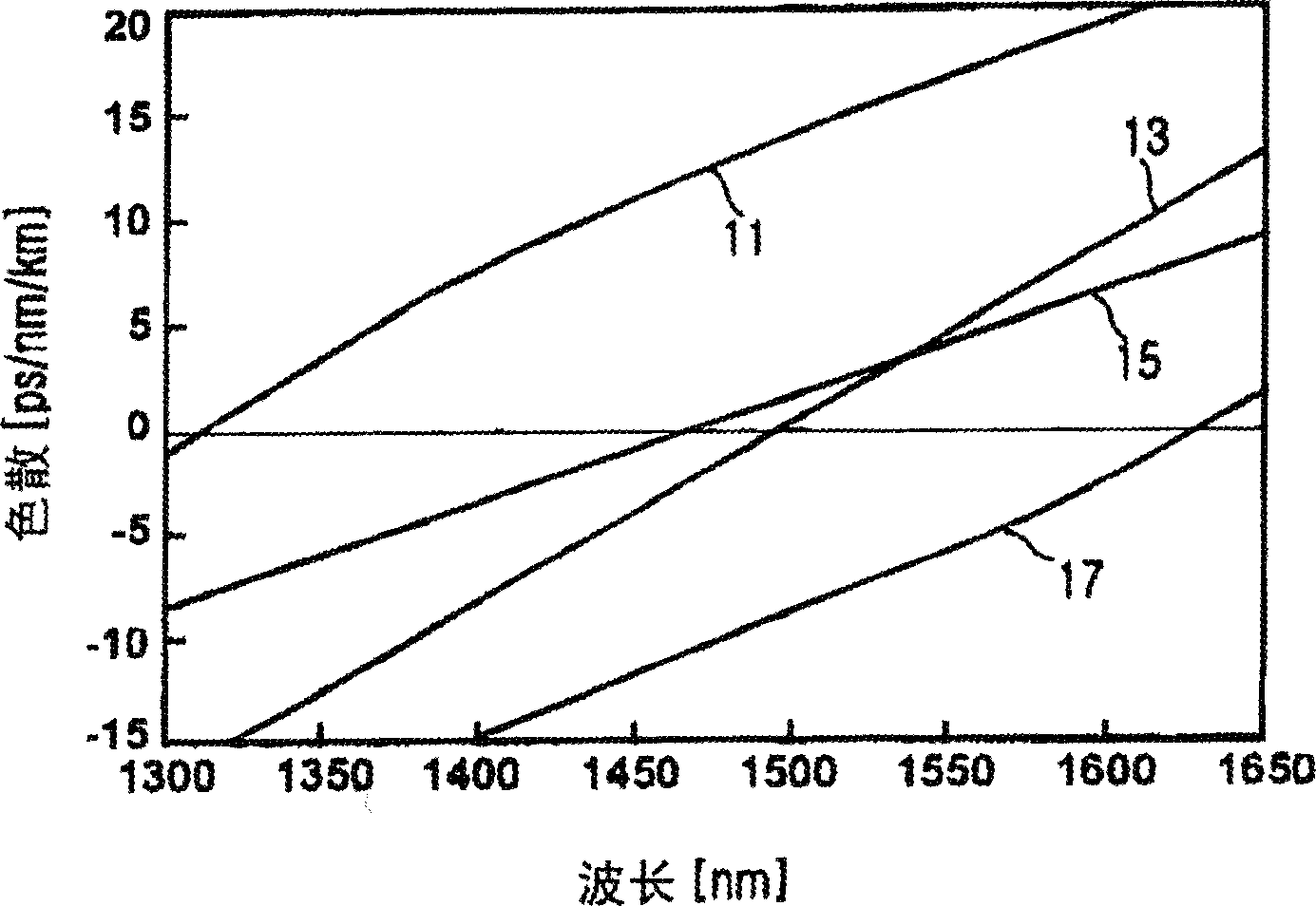
[0028] figure 2 is a graph showing a broadband dispersion managed fiber 100 in accordance with a preferred embodiment of the present invention, and a graph s...


PUM


Abstract

Disclosed is a wide-band dispersion controlled optical fiber. The optical fiber enables the use of optical signals in various wavelength regions in a wavelength division multiplexing mode communication network by controlling the position of the zero dispersion wavelength, and enables long distance transmission by controlling dispersion slope and bending loss. Furthermore, there is an advantage in that the optical fiber enables not only short distance transmission but also middle / long distance transmission using a single type of optical fiber because the optical fiber is controlled to have negative dispersion values in the O-band wavelength region and positive dispersion values with small deviations in the C-band and L-band wavelength regions.

Description

technical field [0001] The present invention relates to an optical fiber, and more particularly, to a broadband dispersion-controlled optical fiber that can be used for medium / long-distance transmission while using broadband optical signals. Background technique [0002] In an optical transmission network for transmitting high-capacity information in a wavelength division multiplexing (WDM) manner, N optical signals having different wavelengths are multiplexed and simultaneously transmitted through one optical fiber. In principle, the C-band wavelength range (1530nm to 1565nm) and the L-band wavelength range (1570nm to 1605nm) are used in optical signals transmitted through optical fibers, in which the transmission characteristics of optical signals are better. Meanwhile, in order to perform broadband / large-capacity transmission in an optical communication network using the WDM method, fruitful research has been made so that the O-band wavelength range (1285nm to 1330nm) and...

Claims


Application Information

Patent Timeline
Patent Type & Authority Applications(China)
IPC IPC(8): G02B6/02G02B6/00G02B6/036H01S3/067H01S3/30
CPCG02B6/02223G02B6/0281G02B6/03633G02B6/02014G02B6/02238H01S3/06725H01S3/06729H01S3/302G02B6/02
Inventor 曹正植都文显杨镇成车相澔韩周创张允根郭起汶
Owner SAMSUNG ELECTRONICS CO LTD
Why Eureka
Try Eureka