Method of image correction in continuous scanning

An image correction and scanning line technology, applied in image communication, electrical components, etc., can solve the problems of unable to correct scanned images, time-consuming, color cast, etc.

Inactive Publication Date: 2004-08-18
TRANSPACIFIC SYST
View PDF0 Cites 1 Cited by
  • Summary
  • Abstract
  • Description
  • Claims
  • Application Information

AI Technical Summary

Problems solved by technology

[0007] From the above, it can be known that the conventional method of image correction during continuous scanning (including multiple scans and batch scans) has a disadvantage: in the case of multiple scans, it is necessary to repeatedly create a gray value calibration curve for each scan , it will take a lot of time; and in the case of batch scanning, because it only scans the calibration map once and has only one gray value calibration curve, it will be impossible to correct the scanned image when scanning multiple times continuously, and it is easy to have Color cast occurs

Method used


Image

  • Method of image correction in continuous scanning
  • Method of image correction in continuous scanning
  • Method of image correction in continuous scanning

Examples


Embodiment Construction

[0017] The present invention proposes a method for image correction during continuous scanning applied in scanners. This method can be used to correct the gray value of scanned images during multiple scanning and batch scanning, which can effectively improve the traditional multiple scanning There are many shortcomings caused by the method of image correction when scanning in batches.

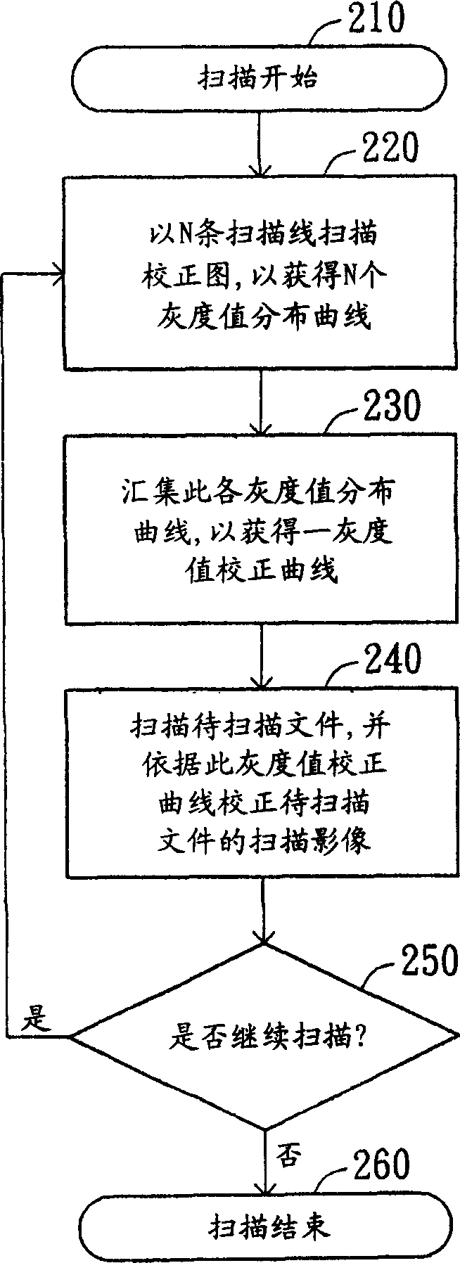
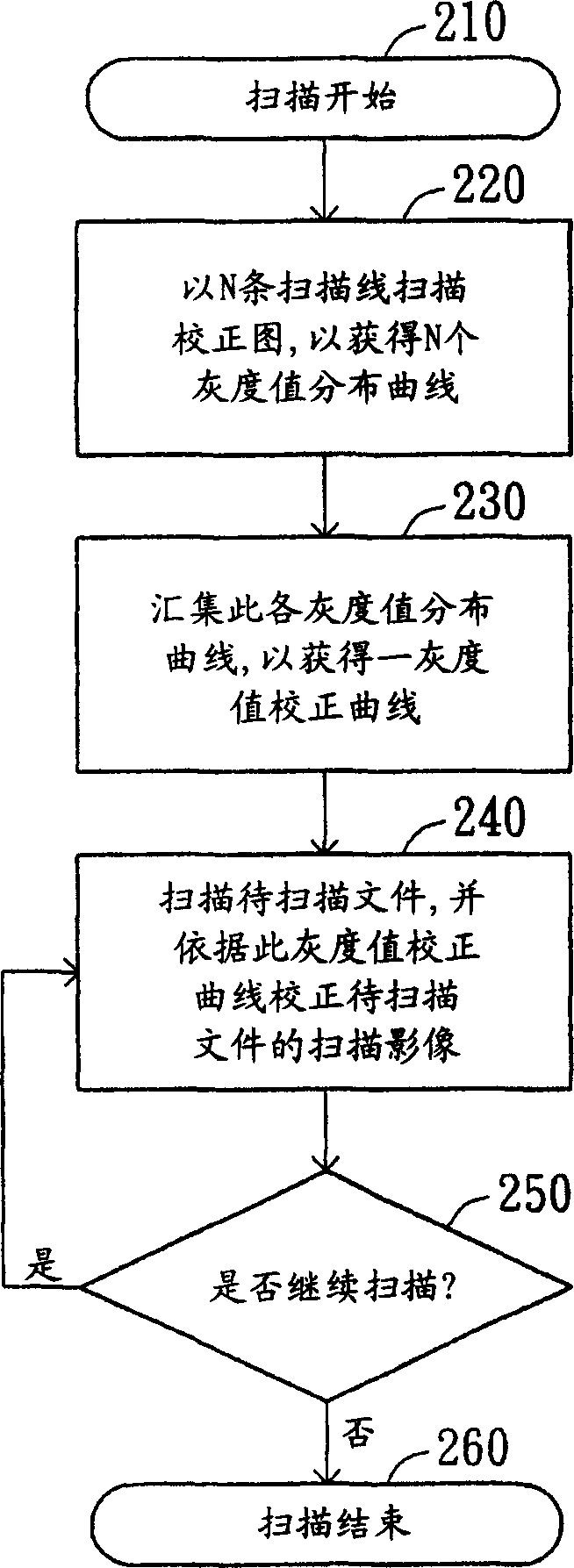
[0018] Please refer to Figure 3A , which shows a flow chart of a method for image correction applied in a scanner during continuous scanning according to a preferred embodiment of the present invention. In the method for image correction during continuous scanning, the contents of steps 210 to 260 are the same as those in the conventional method for image correction during multiple or batch scanning. Its difference is that in step 250, when judging whether to continue scanning, if continue scanning (performing multiple scans or batch scans belonging to continuous scanning), then proceed to st...


PUM


Abstract

The invention discloses a method for correction in sequential scanning for the document scanning in a scanner, the method comprises the steps of, first, scanning a calibration plot using multiple first scanning lines, then obtaining a plurality of first gray scale value distribution curves corresponding to these first scanning lines, collecting these first gray scale value distribution curves, later scanning the calibration plot using multiple second scanning lines, obtaining a plurality of second temporary gray scale value distribution curves corresponding to these second scanning lines, collecting these second gray scale value distribution curves so as to obtain these temporary gray scale value distribution curves, finally obtaining the second gray scale value distribution curves.

Description

technical field [0001] The invention relates to an image correction method, in particular to an image correction method used in a scanner during continuous scanning. Background technique [0002] Among the many peripherals of a personal computer, the image scanner can be said to be one of the basic equipment. Generally speaking, the scanned image of the document to be scanned often needs to be corrected for the gray value due to the uneven illumination of the irradiating light source, so that the scanned image will not have color cast. [0003] Please refer to figure 1 , which is a schematic diagram of a scanning chassis in a scanner scanning a calibration map in advance before scanning a document to be scanned. The scanner 100 is configured with a scanning optical machine 110 , a guide rail 120 and a scanning platform 140 , and the calibration map 130 is configured on a side of the scanner 100 . [0004] The optical scanning machine 110 is driven to move on the guide rai...

Claims


Application Information

Patent Timeline
Patent Type & Authority Applications(China)
IPC IPC(8): H04N1/04H04N1/387
Inventor 刘荣基
Owner TRANSPACIFIC SYST
Why Eureka
Try Eureka