Assembly structure of magnetic head assembly unit

An assembly structure and assembly technology, applied in the configuration/installation of the recording head, support head, fixed installation, etc., can solve the problems of increasing the number of parts, increasing the number of parts, and not being able to install low-cost magnetic head assemblies.

Inactive Publication Date: 2004-08-25
ALPS ALPINE CO LTD
View PDF3 Cites 0 Cited by
  • Summary
  • Abstract
  • Description
  • Claims
  • Application Information

AI Technical Summary

Problems solved by technology

[0007] However, in the assembly structure described in the above-mentioned Patent Document 1, in order to fix the screw, it is necessary to provide a protrusion on the magnetic head assembly, and there is a problem that the molding of the magnetic head assembly is troublesome.
In addition, since screws are required, the number of parts increases, and since a step of tightening screws is required during mounting, the magnetic head assembly cannot be mounted at low cost.
[0008] In addition, in the assembly structure described in the above-mentioned Patent Document 2 or 3, in addition to the magnetic head assembly and the substrate, since additional components are required, the number of components increases, and the magnetic head assembly cannot be mounted at low cost.

Method used


Image

  • Assembly structure of magnetic head assembly unit
  • Assembly structure of magnetic head assembly unit
  • Assembly structure of magnetic head assembly unit

Examples


no. 1 Embodiment

[0045] Hereinafter, a first embodiment of the present invention will be described with reference to the drawings.

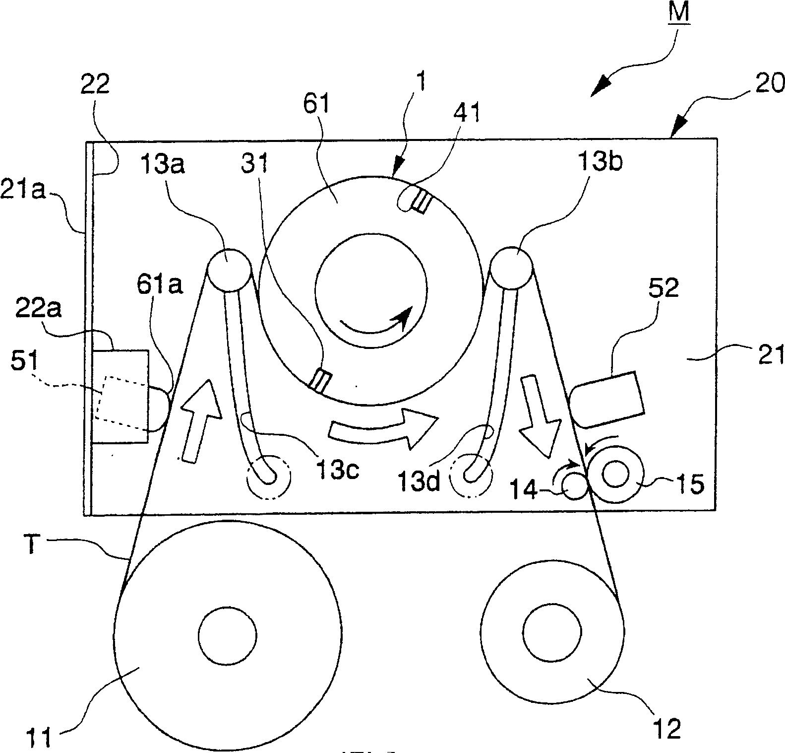
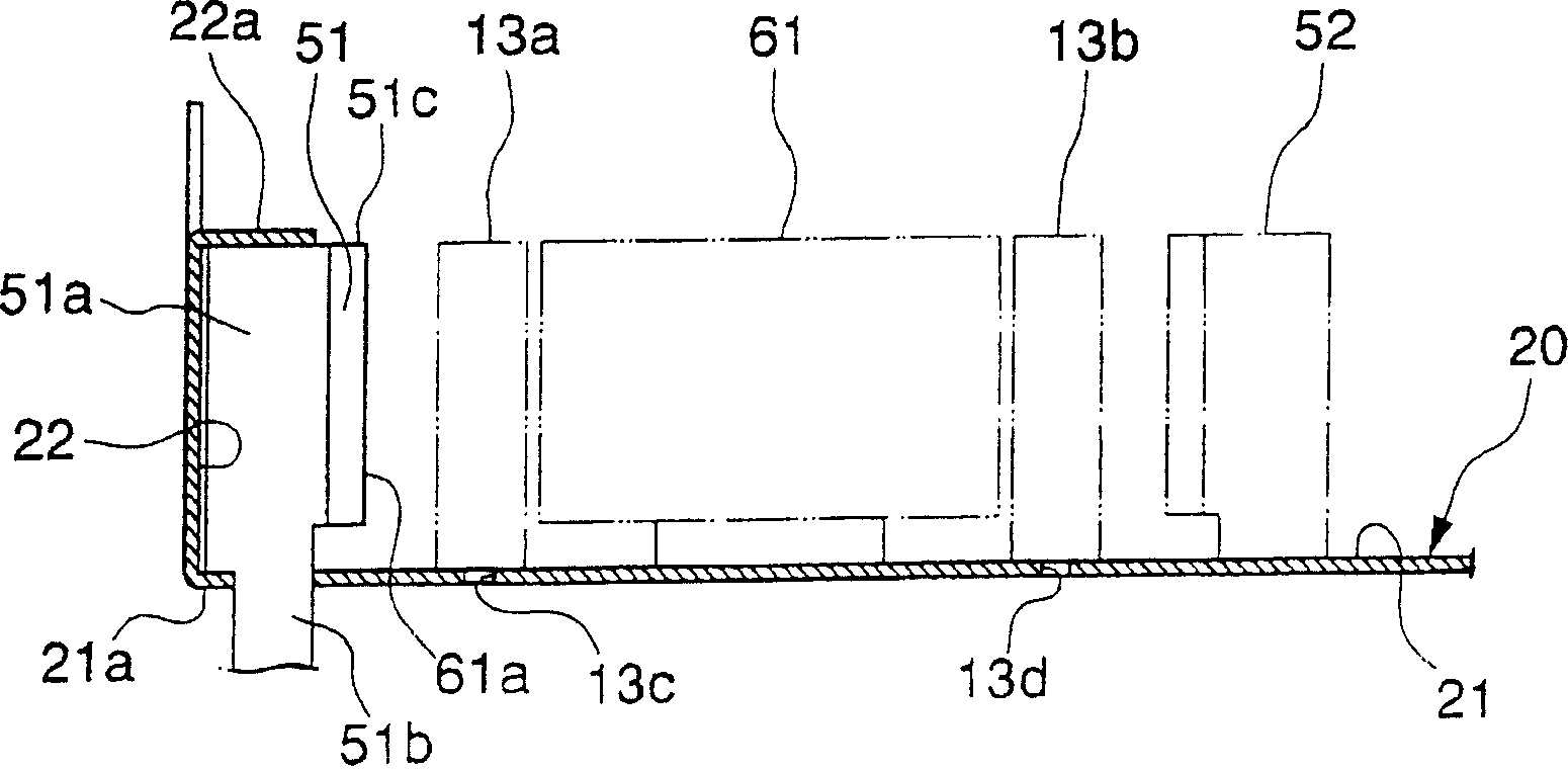
[0046] figure 1 It is a schematic plan view showing a magnetic tape medium recording and reproducing apparatus M having the magnetic head assembly of the present invention. figure 2 A schematic front view showing the magnetic tape medium recording and reproducing apparatus M.

[0047] figure 1 and figure 2 The tape media recording and reproducing device M shown is a device used for electrical appliances such as a VTR, and has a tape loading path that winds a tape medium T drawn out from a tape roller 11 on a rotary drum 1 driven in one direction. In the tape load path, such as figure 1As shown, there are: a pair of guide columns 13a, 13b, which are respectively arranged on the upstream side and the downstream side of the rotating drum 1, to guide the tape medium T drawn out from the tape roller 11 to wind on the rotating drum 1; the driving wheel 14 is prov...

no. 2 Embodiment

[0061] under, Figure 7 A plan view of main parts showing the assembly structure of the magnetic head assembly of this embodiment, Figure 8 A front view of main parts showing the assembly structure of the magnetic head assembly of this embodiment.

[0062] In addition, in Figure 7 and Figure 8 Among the components shown, with Figure 1 to Figure 6 The components of the mounting structure of the magnetic head assembly of the first embodiment shown are the same as those of the component elements, and the same reference numerals are assigned to the same components, and the description thereof will be omitted. This embodiment differs from the first embodiment in that a part of the wall plate 22 is bent to provide a side engaging portion 22c, and the side engaging portion 22c is engaged with the side surface 51e of the main body portion 51a.

[0063] Such as Figure 7 and Figure 8 As shown, the side engaging portion 22c is provided on the wall plate 22 of the chassis subs...

no. 3 Embodiment

[0067] under, Figure 9 A plan view of main parts showing the assembly structure of the magnetic head assembly of this embodiment.

[0068] In addition, in Figure 9 Among the components shown, with Figure 1 to Figure 6 The components of the mounting structure of the magnetic head assembly of the first embodiment shown are the same as those of the component elements, and the same reference numerals are assigned to the same components, and the description thereof will be omitted. The present embodiment differs from the first embodiment in that the rear surface portion 51f on the side opposite to the medium sliding surface 61a of the main body portion 51a is brought closer to the wall plate 22 of the chassis base plate 20 .

[0069] Such as Figure 9 As shown, in the magnetic head assembly of this embodiment, the rear surface 51f (rear surface portion) located on the opposite side to the medium sliding surface 61a of the main body portion 51a is formed so as to be close to t...


PUM


Abstract

Provided is a mounting structure of a magnetic head assembly that has the small number of components and can be mounted only by pressing the magnetic head assembly on a prescribed part of a substrate. In the mounting structure for mounting the magnetic head assembly on a chassis base, the chassis base is composed of a bottom plate 21 provided with an insertion hole 21b and a wall plate 22 erected from the bottom plate 21, and part of the wall plate 22 is folded to form an engaging part 22a. The magnetic head assembly is provided with a substantially columnar body part 51a having a medium sliding face and a leg part 51b attached to one end side of the body part 51a. The leg part 51b is inserted in the insertion hole 21b and the body part 51a is engaged with the engaging part 22a.

Description

technical field [0001] The invention relates to an assembly structure for installing a magnetic head assembly on a bottom frame substrate, in particular to an assembly structure for installing a full-width erasing magnetic head for a video tape recorder on the bottom frame substrate. Background technique [0002] Generally, in a home-use video tape recorder (hereinafter abbreviated as WTR), a full erasing magnetic head assembly (hereinafter abbreviated as a magnetic head assembly) for erasing magnetic signals written on a video tape is assembled on the upstream side of the rotary drum. For example, Patent Document 1 below discloses an example in which a magnetic head assembly is fixed to a substrate built in a VTR by tightening screws. In addition, on the chassis board of a common VTR, in addition to the magnetic head assembly, the included rotating drum, the guide post for winding the video tape on the rotating drum, the magnetic head for audio, and the drive wheel for driv...

Claims


Application Information

Patent Timeline
Patent Type & Authority Applications(China)
IPC IPC(8): G11B5/49G11B21/16
Inventor 秋山透关口晃
Owner ALPS ALPINE CO LTD
Why Eureka
Try Eureka