Washing machine

A washing machine and clothing technology, applied in the field of washing machines, can solve the problems of vibration, strong vibration, and reduced performance of washing machines

Inactive Publication Date: 2004-09-08
LG ELECTRONICS INC
View PDF0 Cites 18 Cited by
  • Summary
  • Abstract
  • Description
  • Claims
  • Application Information

AI Technical Summary

Problems solved by technology

[0004] However, in the washing machine according to the conventional art, since the inner tub 114 containing the laundry rotates at a high speed, vibration occurs during dehydration.
A certain degree of vibration can be absorbed by the u

Method used


Image

  • Washing machine
  • Washing machine
  • Washing machine

Examples


Embodiment Construction

[0021] The following will be described in detail with reference to preferred embodiments of the present invention, shown in the accompanying drawings

[0022] Examples of specific implementations.

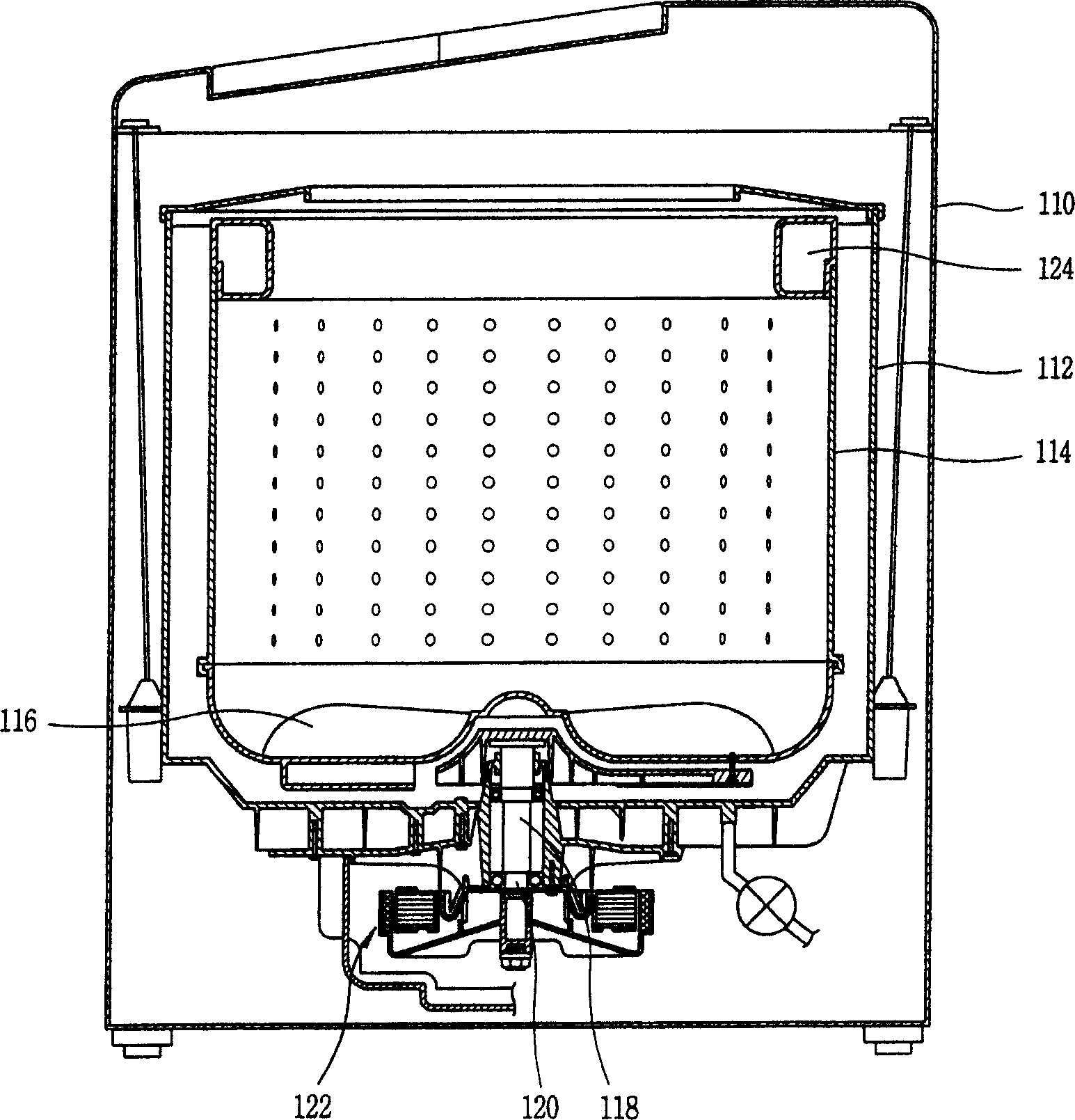
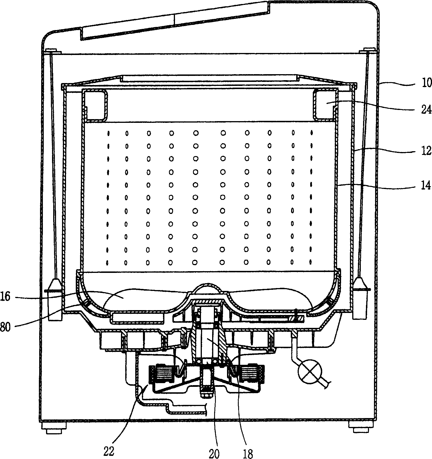
[0023] attached figure 2 shows a longitudinal sectional view of a washing machine according to a first embodiment of the invention;

[0024] The washing machine according to the first specific embodiment of the present invention comprises a casing 10, an outer tub 12, an inner tub 14, a pulsator 16, a hollow dehydration shaft 18, a washing shaft 20, a drive motor 22, an upper Balancer 24 and a lower balancer. Wherein casing 10 forms the exterior shape of washing machine and its top can be opened selectively; Outer tub 12 is placed in the casing 10 and is filled with water; Inner tub 14 is placed in outer tub 12, is used for loading the clothes to be washed, And can rotate to wash, dehydrate clothes; Wave wheel 16 is installed in inner tub 14 and rotates to stir water and the cl...


PUM


Abstract

A washing machine comprises an outer tub disposed in a case and receiving water therein, an inner tub installed in the outer tub, receiving laundry therein and rotated for washing and dewatering the laundry and a lower balancer installed at a lower part of the inner tub for reducing vibration generated during rotation of the inner tub. Accordingly, a lopsidedness and vibration of the inner tub generated during washing and dewatering operations can be prevented.

Description

technical field [0001] The present invention relates to a washing machine, and more particularly to a washing machine comprising a balancer formed at a lower part of a washing tub to reduce vibration generated during rotation of the washing tub. Background technique [0002] Usually, if attached figure 1 As shown, the washing machine includes a casing 110 , an outer tub 112 , an inner tub 114 , a pulsator 116 , a hollow dehydration shaft 118 , a washing shaft 120 , a drive motor 122 and an upper balancer 124 . Wherein the casing 110 forms the appearance of a washing machine and its top can be selectively opened; the outer tub 112 is placed in the casing 110 and filled with water; the inner tub 114 is placed in the outer tub 112 for loading clothes to be washed, and It can rotate to wash and dehydrate clothes; the pulsator 116 is installed in the inner tub 114 and rotates to stir the water and the clothes to be washed; the hollow dehydration shaft 118 is connected with the i...

Claims


Application Information

Patent Timeline
IPC IPC(8): D06F49/02D06F37/12D06F37/24
CPCD06F37/245D06F37/12
Inventor 林熙泰张宰源
Owner LG ELECTRONICS INC
Why Eureka
Try Eureka