Scanning instrument

A scanner and optical scanning technology, applied in the direction of instruments, character and pattern recognition, computer parts, etc., can solve the problems of cost and other problems, and achieve the effect of saving cost, omitting material cost and assembly man-hour

Inactive Publication Date: 2004-09-08
UMAX DATA SYST
View PDF0 Cites 2 Cited by
  • Summary
  • Abstract
  • Description
  • Claims
  • Application Information

AI Technical Summary

Problems solved by technology

[0008] 1. The use of positioning correction sheets for optical scanning modules will inevitably cost costs (including assembly hours)
[0009] 2. The position of the black and white interval of the optical scanning module positioning calibration sheet must be very accurate.

Method used


Image

  • Scanning instrument
  • Scanning instrument
  • Scanning instrument

Examples


Embodiment Construction

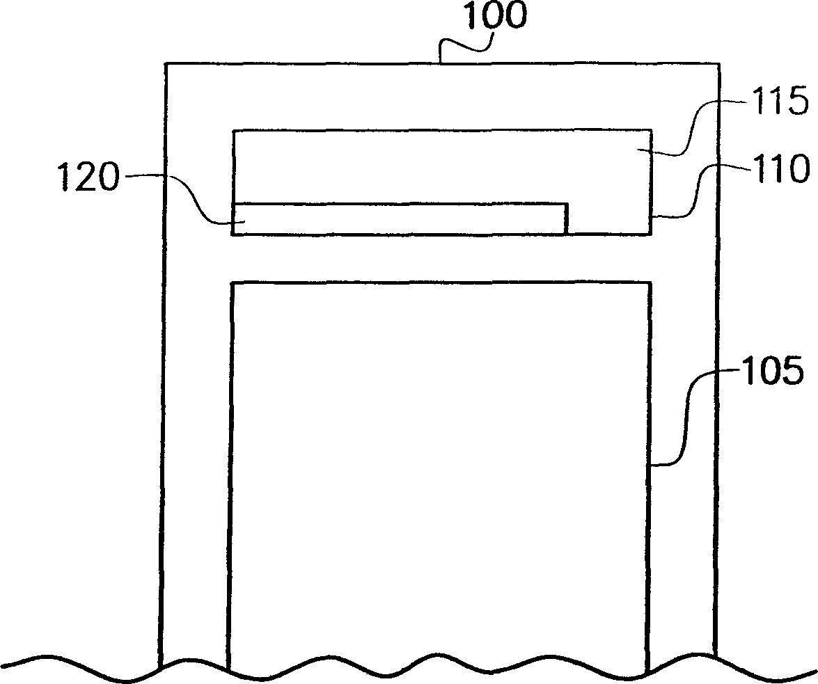
[0024] The invention provides a scanner. The scanner has a casing (which can be divided into an upper casing and a lower casing), and an optical scanning module, a driving device, a guiding device and a control circuit are arranged in the casing. Among them, in order to save the material cost and assembly man-hours of the positioning device of the optical scanning module in the scanner, the present invention considers that an alternative that can scatter light is arranged on the upper casing, such as a bump with a matte surface or a matte surface. , to replace the known optical scanning module positioning calibration sheet.

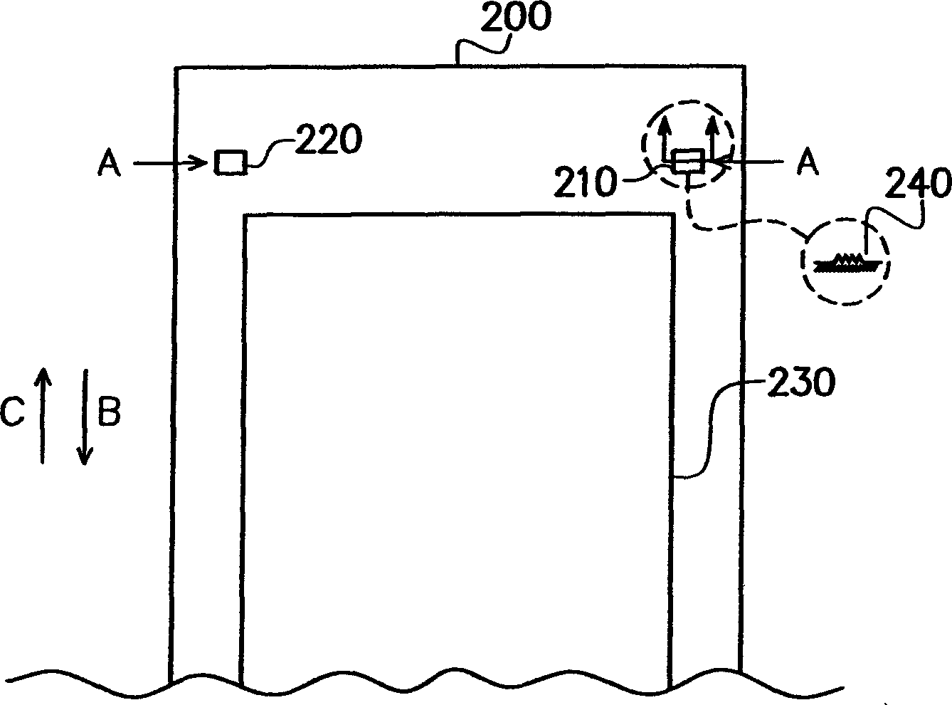
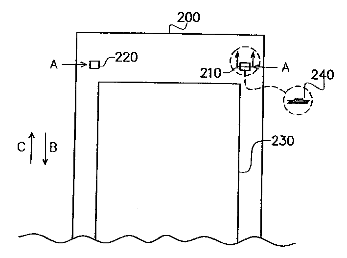
[0025] Please refer to figure 2 , figure 2 What is shown is the inner view of the upper casing of the scanner according to the preferred embodiment of the present invention. exist figure 2 Among them, the upper housing 100 has a scanning window 230 , and beside the scanning window 230 , there are bumps 210 and bumps 220 at appropriate positions corr...


PUM


Abstract

The scanning instrument has fogged raised dot or fogged area beside the scanning window in its upper casing, and the fogged raised dot or fogged area is used in positioning the start point of the scanning path of optical scanning module during scanning the document in the scanning window.

Description

technical field [0001] The present invention relates to a positioning device for an optical scanning module, and in particular to a positioning device for an optical scanning module that does not need to use a calibration sheet for positioning the optical scanning module. Background technique [0002] With the great improvement of computer performance and the high development of Internet and multimedia technology, in addition to using digital camera (Digital Camera, DC) to directly capture image patterns, other image input operations related to documents or pictures need to be done through optical The scanner (Optical Scanner) captures the analog image of text or pattern and converts it into a digital signal output, which helps users to display, recognize (OCR), and Actions such as editing, saving and exporting. [0003] According to the input method of document images, optical scanners can be divided into palm scanners, sheet feed scanners, drum scanners, flatbed scanners,...

Claims


Application Information

Patent Timeline
Patent Type & Authority Applications(China)
IPC IPC(8): G06K9/20
Inventor 萧俊义陈聪颖
Owner UMAX DATA SYST
Why Eureka
Try Eureka