Image scanning device and commercial equipment using the same device

A technology of an image scanning device and an image sensor, which is applied to the equipment of the electric recording process applying the charge pattern, the printing device, the printing equipment, etc., can solve the problems of complex setting pressure and pressing on the sensor, etc., and avoid document transportation. Error, the effect of avoiding reading (scanning) error

Inactive Publication Date: 2004-09-08
SEIKO EPSON CORP
View PDF1 Cites 4 Cited by
  • Summary
  • Abstract
  • Description
  • Claims
  • Application Information

AI Technical Summary

Problems solved by technology

[0014] but, Figure 15 The conventional scanner shown adjusts the force applied to the original and platen by varying the compression of only one spring 103, and thus uses only one spring rate to set the applied pressure
Therefore, the problem with this scanner is that it is necessary to limit the range of applied pressure that can be adjusted, and it is not possible to press thin and thick originals of different thicknesses against the sensor with the pressure for a specific original.
[0015] Figure 15 The pressure adjustment of the traditional scanner shown requires the operator to manually manipulate the pressure adjustment gear to adjust the pressure every time the thickness of the original changes, and it is complicated to set the pressure accurately

Method used


Image

  • Image scanning device and commercial equipment using the same device
  • Image scanning device and commercial equipment using the same device
  • Image scanning device and commercial equipment using the same device

Examples


no. 1 example

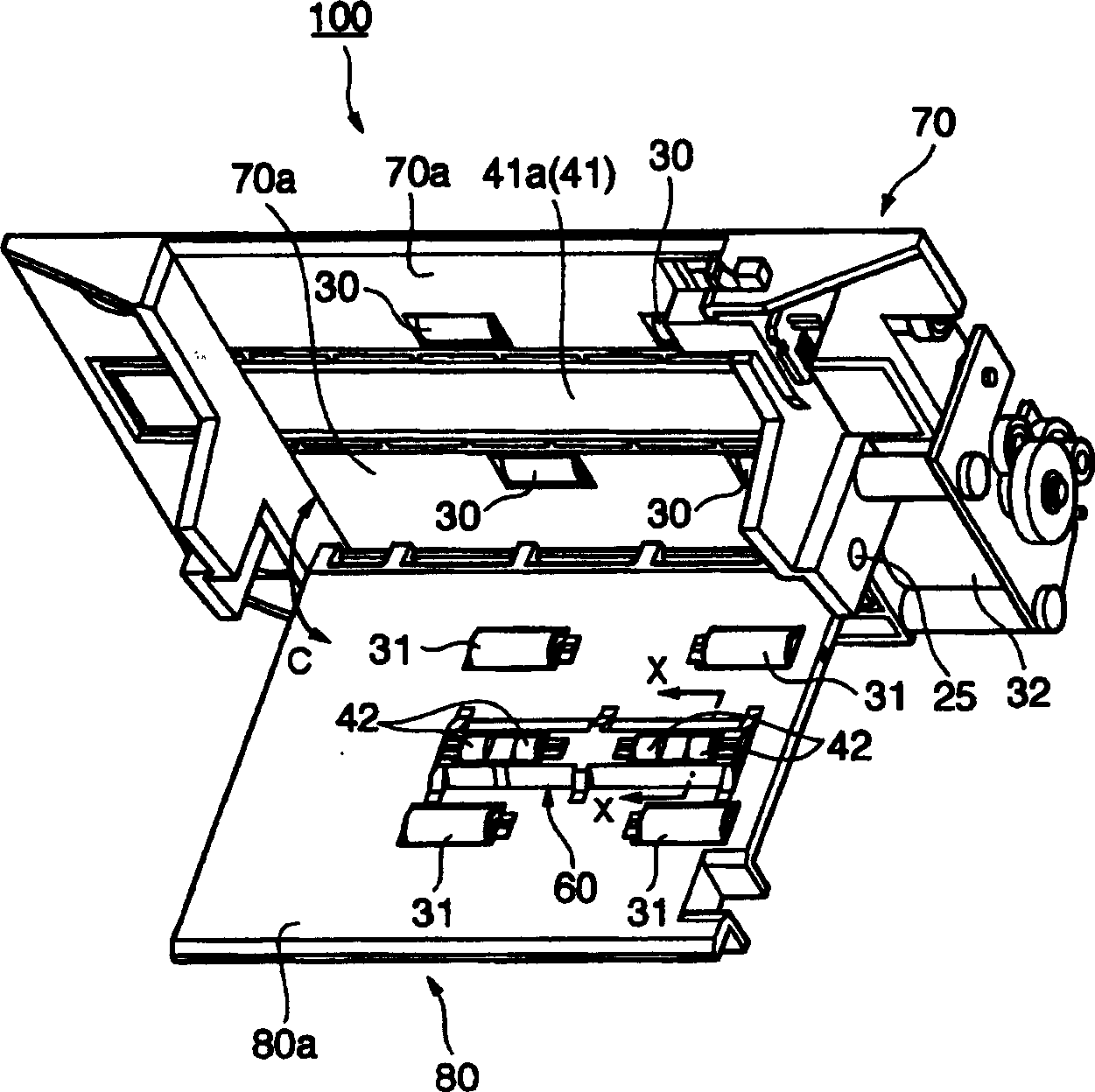
[0057] Use the attached Figures 2 to 5 A more specific application of the pressure generating mechanism 50 described above will be described. figure 2 is the perspective view of the scanner, while image 3 is a partial perspective view of the main parts of the scanner. Figure 4 with 5 is through figure 2 A cross-sectional view taken along the line X-X. Figure 4 is the cutaway view when inserting a thin original, while Figure 5 is a sectional view when a thick original is inserted.

[0058] figure 2 The illustrated scanner 100 utilizes a paper guide 80 (corresponding to the fixed guide 10 in FIG. figure 2 The parts of the hinge 25 that are freely opened and closed in the direction shown by the arrow in the arrow are installed on the main frame 70 including the drive system.

[0059] A motor 32 , four paper feed drive rollers 30 connected to and driven by the motor 32 , and a contact image sensor 41 are mounted on the main frame 70 .

[0060] The sensor 41 is pr...

no. 2 example

[0100] Refer below Figures 7 to 14 Another embodiment of the scanner according to the present invention will be described.

[0101] Figure 7 The shown perspective view represents a business device 200 equipped with a scanner 110 according to a second embodiment of the present invention.

[0102] This business device 200 is a multifunction printer equipped with a scanner, and can print on roll paper (not shown) and slip paper (slip paper) (not shown), and further, can also be obtained from Scan and obtain information on slip structures and cards.

[0103] The commercial equipment 200 has a bottom case part 211 , a front case part 212 and a top cover unit 213 which are integrally formed. The bottom case portion 211 accommodates a paper roll (not shown), and has a printing mechanism for printing on roll paper pulled from the paper roll. The front case part 212 is disposed in front of the bottom case part 211 and has a sheet feed path 221 for feeding a sheet between the fron...


PUM


Abstract

Scanning errors and document feed errors are prevented by pressing originals, including thin originals and thick originals of greatly different thickness, to the scanning surface (1a) of an image sensor (1) with pressure appropriate for the respective original. A pressure-generating mechanism (50) presses the original against the scanning surface (1a) by using a selected one of multip.

Description

technical field [0001] The present invention relates to an image scanning device using an image sensor, and to a business device using the image scanning device. Background technique [0002] An image scanning device, hereinafter referred to simply as a "scanner", uses a sensor in contact with an image, and image scanning devices currently in use can scan a document from a printed image by holding the document in contact with the scanning surface of the sensor. File captures images electronically. This scanning surface is typically a glass plate and captures the image from the document while pressing the document against the glass with high precision and with just the right amount of force. [0003] Conventional scanners with contact image sensors therefore typically transport the document onto the scanning surface while pressing the document against the scanning surface, for example with a spring. Some scanners are capable of adjusting the pressure of the document against...

Claims


Application Information

Patent Timeline
Patent Type & Authority Applications(China)
IPC IPC(8): G03B27/62G03G15/00G06K9/20G06T1/00G07D7/16H04N1/00H04N1/04H04N1/12H04N1/193
CPCH04N2201/0456G03G2215/00253G03G15/60H04N1/1215G03G2215/00248H04N1/193
Inventor 降幡秀树
Owner SEIKO EPSON CORP
Why Eureka
Try Eureka