Electric circuit breaker

A technology for circuit breakers and circuits, which is applied to circuits, circuit breaker parts, electric switches, etc., and can solve problems such as slow movement of arc ends, inability of arc points to travel continuously, and inability to obtain high-speed interruption performance.

Inactive Publication Date: 2004-09-08
MITSUBISHI ELECTRIC CORP
View PDF2 Cites 3 Cited by
  • Summary
  • Abstract
  • Description
  • Claims
  • Application Information

AI Technical Summary

Problems solved by technology

[0004] In such a circuit breaker, especially when the short-circuit current is interrupted, the arc point generated between the contact pair cannot continuously travel to the circuit breaker (a structure in which the arc travel path is discontinuous and requires commutation), or Between the contact pair and the arc extinguishing device, the section along the arc traveling direction of the arc traveling surface is a convex surface, and t

Method used


Image

  • Electric circuit breaker
  • Electric circuit breaker
  • Electric circuit breaker

Examples


Embodiment 1

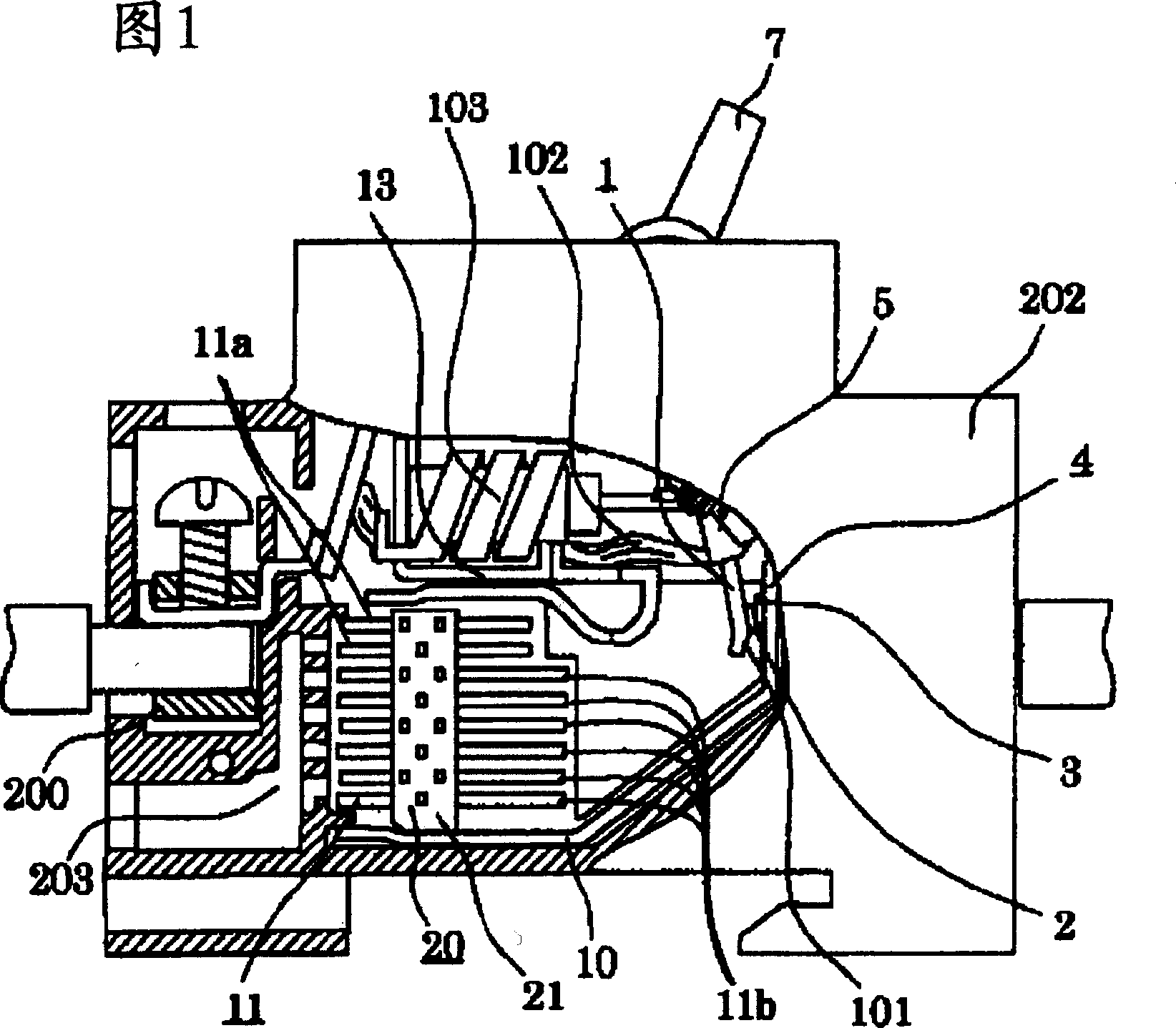
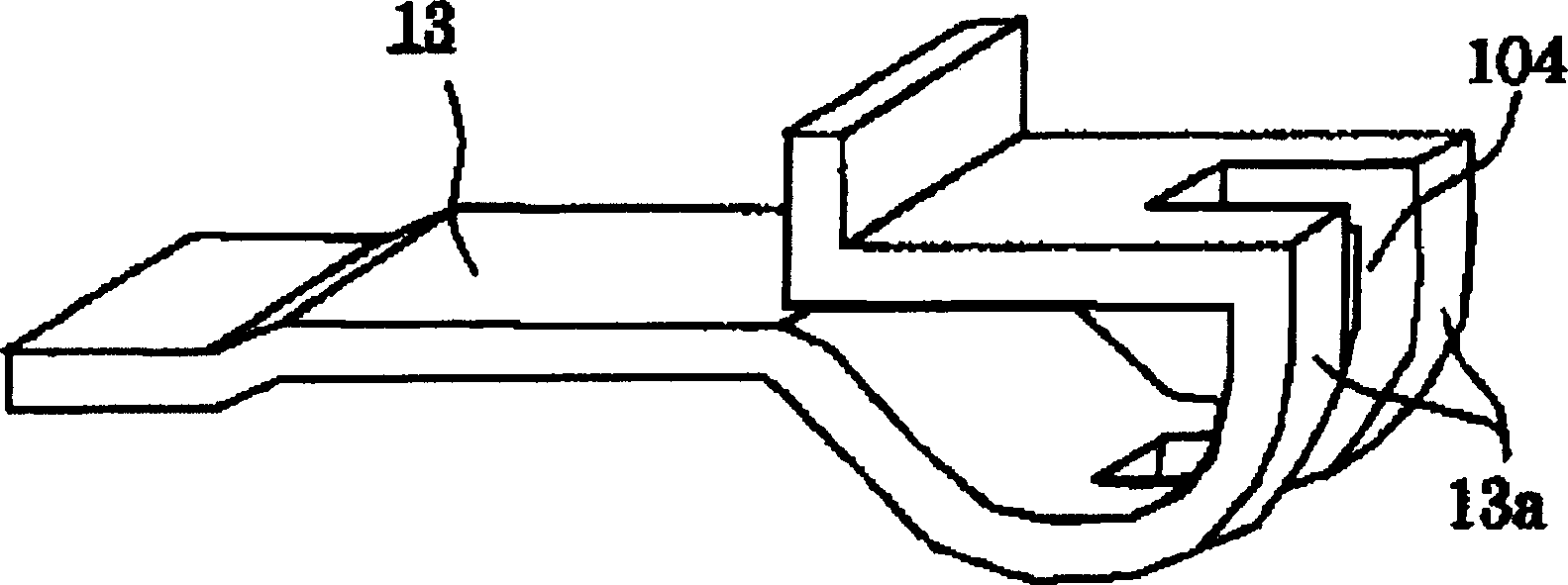
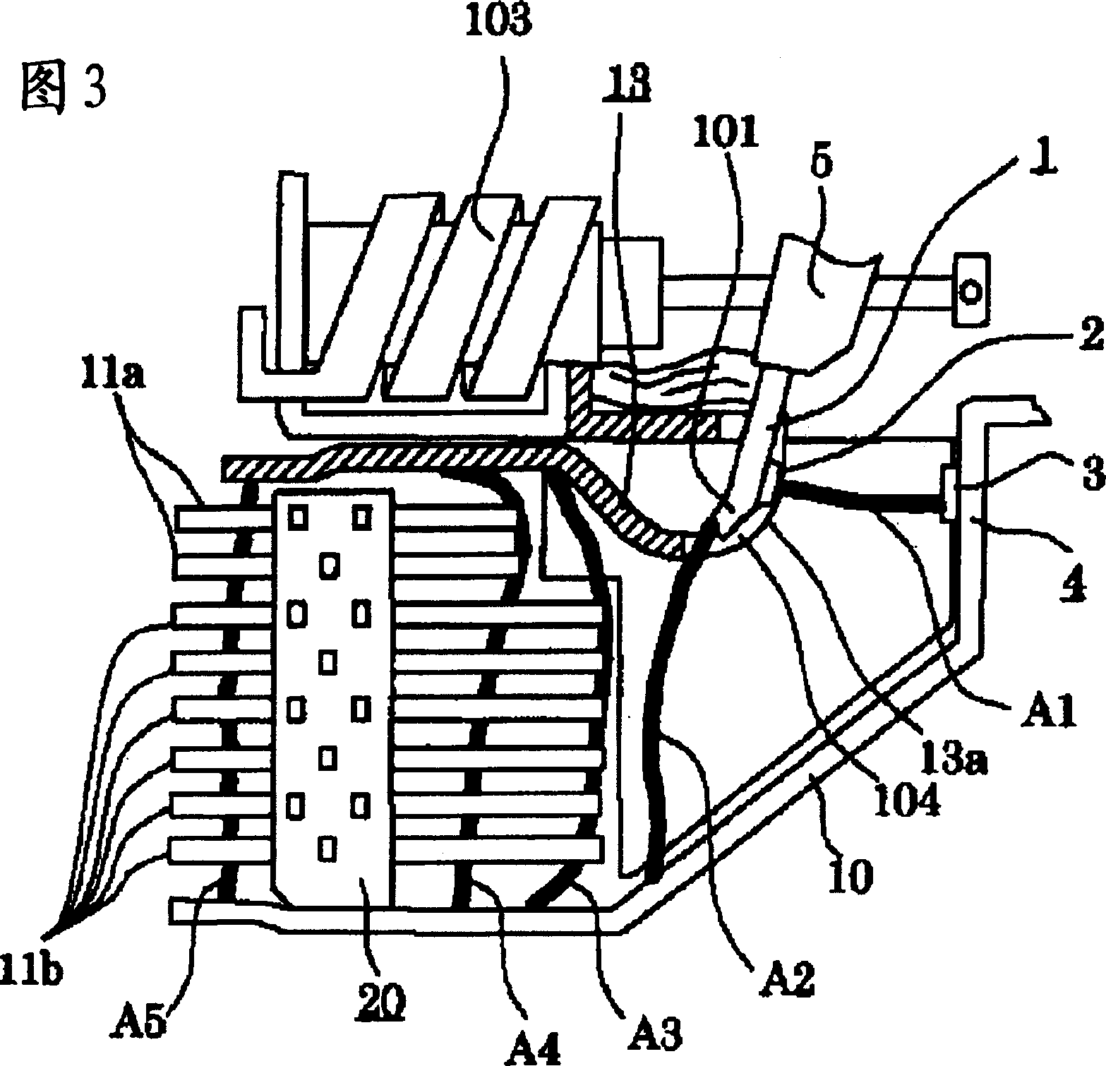
[0030] Figure 1~ Figure 4 It is a figure for explaining the circuit breaker of Example 1 of this invention, More specifically, FIG. figure 2 It is an enlarged perspective view showing the arc guide on the side of the movable adapter, and FIG. 3 is a partial cross-sectional view of the main part for schematically showing the behavior of the arc during the breaking operation, Figure 4 It is a plan view of the arc extinguishing plate viewed from the arc guide on the side of the movable adapter.

[0031] As shown in FIG. 1 , generally in such a circuit breaker, it is provided in a frame body 202 made of insulators: a pair of terminals 200 and 201 (201 not shown) connected to an external circuit; The adapter 4; the movable contact 2 that is connected and separated from the fixed contact 3, and the movable adapter 1 forming an adapter pair with the fixed adapter 4; the switch mechanism 5 that drives the movable adapter 1; responds to the overcurrent to make the The switch mecha...

Embodiment 2

[0052] Figure 5 It is a figure for explaining the circuit breaker of Example 2 of this invention, More specifically, it is a plan view which looked at the arc-extinguishing plate from the arc guide side of a movable adapter side.

[0053] Compared with the circuit breaker of Embodiment 1, the circuit breaker of this embodiment has different shapes of the ends of the contacts 2 and 3 of the arc extinguishing plate 11a near the arc guide member on the side slower than the arc extinguishing device 20, Other structures are the same as in Embodiment 1. Therefore, points different from Example 1 will be mainly described below.

[0054] In this example, if Figure 5 As shown, the other arc extinguishing plate 11b is configured in the same plate shape with a wedge-shaped cutout as in Embodiment 1, and the arc extinguishing plate 11a near the arc guide 13 on the side of the movable adapter is configured to have a larger cutout than the other arc extinguishing plate 11b. The width (...

Embodiment 3

[0060] Figure 6 It is FIG. 3 for explaining Example 3 of the present invention, and more specifically, it is a partial cross-sectional view of main parts.

[0061] Compared with the circuit breaker of the first embodiment, the circuit breaker of this embodiment differs in the structure of the arc guide member on the side of the movable adapter, and the other structures are the same as those of the first embodiment. Therefore, points different from Example 1 will be mainly described below.

[0062] In Embodiment 1, in order to shorten the time required for commutation from the angular portion 101 of the arc point on the side of the movable joint 1 to the arc guide 13 on the side of the movable joint, the arc is guided on the side of the movable joint. The member 13 is provided with a protruding portion 13a that protrudes toward the fixed contact 3 side and has a slit 104 through which a part of the movable adapter 1 passes when the movable contact 2 leaves, but in this embodi...


PUM


Abstract

To provide a circuit breaker which can bring the whole arc to an arc-extinguishing device quickly and has a high breaking performance even when breaking a high current such as a short circuit current. The circuit breaker comprises a fixed contact piece 4 having a fixed contact point 3; a movable contact piece 1 having a movable contact point 2 making contact with/coming off the fixed contact point; an arc-extinguishing device 20 which injects an arc onto a plurality of arc-extinguishing plates 11, partitions the arc, and extinguishes the arc, where the arc occurs between a pair of contact points composed of the fixed contact point and the movable contact point, when the movable contact point comes off; and a pair of fixed contact side steering members and movable contact side steering members 10, 101, 13, which steer the arc from the pair of the contact points to the arc-extinguishing device. The surface direction component of arc-extinguishing plate for the arc-extinguish plates 11a placed at the latter arrival side of the arc to the arc-extinguishing device at a distance between the fixed contact point and an arc injection position on the end surface side of the pair of the contact points is larger than the similar surface direction component for the other arc-extinguish plates 11b. The surface direction component of arc-extinguishing plate for the arc-extinguish plates 11a placed at the latter arrival side of the arc to the arc-extinguishing device at a distance between the fixed contact point and an arc injection position on the end surface side of the pair of the contact points is larger than the surface direction component of arc-extinguishing plate for the other arc-extinguish plates 11b, at a distance between the fixed contact point and an arc injection position on the end surface side of the pair of the contact points.(C)2004,JPO&NCIPI.

Description

technical field [0001] The present invention relates to a circuit breaker that interrupts a circuit when an overcurrent such as an overload current or a short-circuit current occurs. Background technique [0002] In the conventional circuit breaker, the main circuit formed after the contact part is inserted between the power supply side terminal and the load side terminal, if an excessive current flows through the main circuit when the contact part is closed, the contact part is forced to In an open circuit breaker, a pair of arcs are provided that are electrically connected to the contacts constituting the contact part, extend in the direction of the electromagnetic force acting on the arc through interaction with the magnetic field around the contact part, and are arranged opposite to each other. The traveling plate forms the side walls of the space in which the two arc traveling plates are accommodated, so that the distance between them expands toward the direction of the...

Claims


Application Information

Patent Timeline
IPC IPC(8): H01H9/36H01H9/34H01H9/38H01H73/18
Inventor 三桥孝夫池田龙典
Owner MITSUBISHI ELECTRIC CORP
Why Eureka
Try Eureka