Dual-head electric toothbrush

An electric toothbrush and double brush head technology, applied in the fields of dentistry, tooth cleaning, medical science, etc., can solve the problems of poor tooth surface cleaning effect, difficult to remove dirt between teeth, and unfavorable tooth protection, so as to improve tooth brushing efficiency and good Teeth, tooth protection effect

Inactive Publication Date: 2004-09-15
林 辉明
View PDF0 Cites 7 Cited by
  • Summary
  • Abstract
  • Description
  • Claims
  • Application Information

AI Technical Summary

Problems solved by technology

[0002] Existing electric toothbrush, its brush head or is rotating brush head, and bristle rotates forward and backward around toothbrush handle, although can effectively remove the dirt on tooth surface, but is difficult to remove the dirt in teeth crevice; Or is swinging brush head, bristle is vertical Swinging back and forth in the direction of the toothbrush handle can effectively remove the dirt between the teeth, but the cleaning effect on the tooth surface is not good
Using the above two electric toothbrushes to brush your teeth will take a lot of time to clean your teeth comprehensively and the effect is not good, which is not conducive to protecting your teeth

Method used


Image

  • Dual-head electric toothbrush
  • Dual-head electric toothbrush
  • Dual-head electric toothbrush

Examples


Embodiment 1

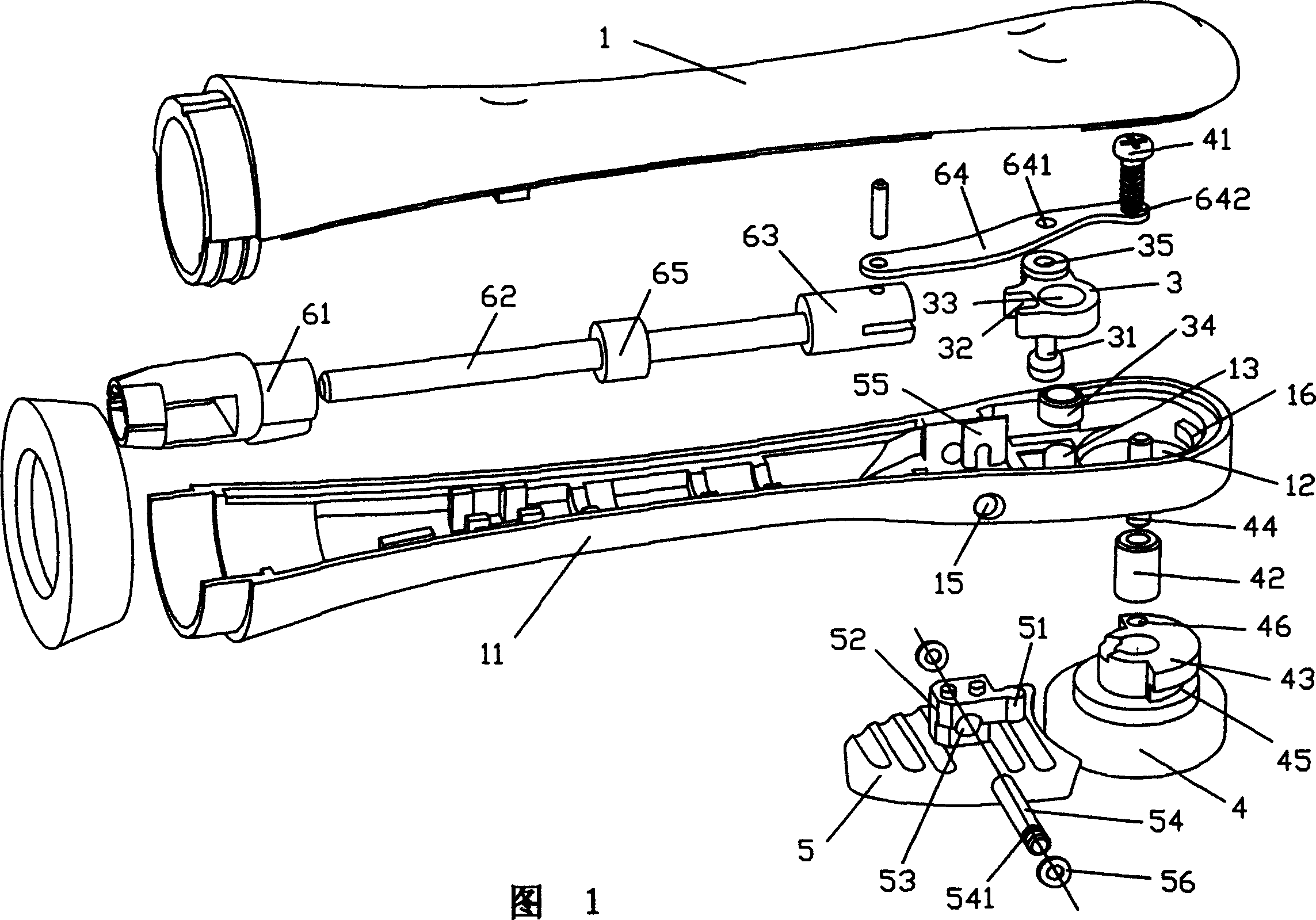
[0027] In this embodiment, the rotating brush head 4 is in the front, and the swinging brush head 5 is in the back, as shown in Figure 1. Correspondingly, a circular hole 12 is opened at the front end of the bottom wall of the lower cover 11 of the toothbrush handle, and a circular hole 12 is opened behind the circular hole 12 A through hole of the shift block is used to install the rotating brush head 4 and the swinging brush head 5 respectively.

[0028] The components of the electric toothbrush and their connection are detailed as follows:

[0029] As shown in Figure 1, the inner cavity of the toothbrush handle 1 is equipped with a connecting rod assembly 6, including a power joint 61, a steel shaft 62, a pull rod 63 and a pull tab 64 hinged to the end of the pull rod 63 that are sequentially connected from back to front. . The power joint 61, the tie rod 63 and the steel shaft 62 are all threaded connections, and the power joint 61 at the rear end is connected to the output sh...

Embodiment 2

[0039] This embodiment is basically the same as the first embodiment. The difference is that the rotating brush head 4 is in the back and the swing brush head 5 is in the front. Figure 5 Correspondingly, the shift block through hole 14 is opened at the front end of the bottom wall of the lower cover 11 of the toothbrush handle, and the circular hole 12 is located behind the shift block through hole 14 for installing the swing brush head 5 and the rotating brush head 4, respectively.

[0040] In addition; the connection mode of the rotating brush head 4 and the toothbrush handle lower cover 11 is also different, and the details are as follows:

[0041] Such as Figure 5 As shown, the back of the bristles of the rotating brush head 4 is fixedly protruding with a circular table 48, the circular table 48 has a central hole 482, and a convex key 481 is provided on the side wall of the circular table 48. During installation, after inserting the round table 48 into the round hole 12 from ...


PUM


Abstract

The present invention relates to an electric toothbrush with two brush heads. It includes a rotary brush head and a swinging brush head which are mounted in the front part of toothbrush handle and respectively rotatably and movably connected with lower cover of toothbrush handle, in the inernal cavity of the toothbrush handle a connecting bar component whose one end is connected with electric device and another end is respectively connected with rotary brush head and driving wheel, and a shifting key mounted on the back surface of swinging brush head can be fallen into recessed groove of one side driving wheel, the described is limited on the track perpendicular to the axis of toothbrush handle. Said invention is high in tooth-brushing efficiency, and good in tooth-cleaning and tooth-protecting effect.

Description

Technical field [0001] The invention relates to a toothbrush for daily necessities, in particular to an electric toothbrush driven by an independent power source. Background technique [0002] The brush head of the existing electric toothbrush is either a rotating brush head, and the bristles rotate around the toothbrush handle. Although it can effectively remove the dirt on the tooth surface, it is difficult to remove the dirt between the teeth; or it is a swinging brush head with the bristles vertical. Swinging back and forth in the direction of the toothbrush handle can effectively remove the dirt between the teeth, but the cleaning effect on the surface of the teeth is not good. To use the above two electric toothbrushes to brush your teeth, it takes more time to clean your teeth and the effect is not good, which is not conducive to tooth protection. Summary of the invention [0003] The technical problem to be solved by the present invention is to provide an electric toothb...

Claims


Application Information

Patent Timeline
Patent Type & Authority Applications(China)
IPC IPC(8): A61C17/26A61C17/34
Inventor 林辉明
Owner 林 辉明
Why Eureka
Try Eureka