Automatic charging system and method for cleaning robot

A technology for cleaning robots and automatic charging, which is applied in the field of cleaning robots and can solve problems such as increasing the cost of charging systems

Inactive Publication Date: 2004-09-22
LG ELECTRONICS INC
View PDF0 Cites 39 Cited by
  • Summary
  • Abstract
  • Description
  • Claims
  • Application Information

AI Technical Summary

Problems solved by technology

Therefore, fixedly installing multiple infrared sensors on the cleaning robot to receive the infrared signal output by the charging part in a short time will increase the cost of realizing the charging system of the cleaning robot

Method used


Image

  • Automatic charging system and method for cleaning robot
  • Automatic charging system and method for cleaning robot
  • Automatic charging system and method for cleaning robot

Examples


Embodiment Construction

[0037] Reference will now be made in detail to the preferred embodiments of the present invention, examples of which are illustrated in the accompanying drawings.

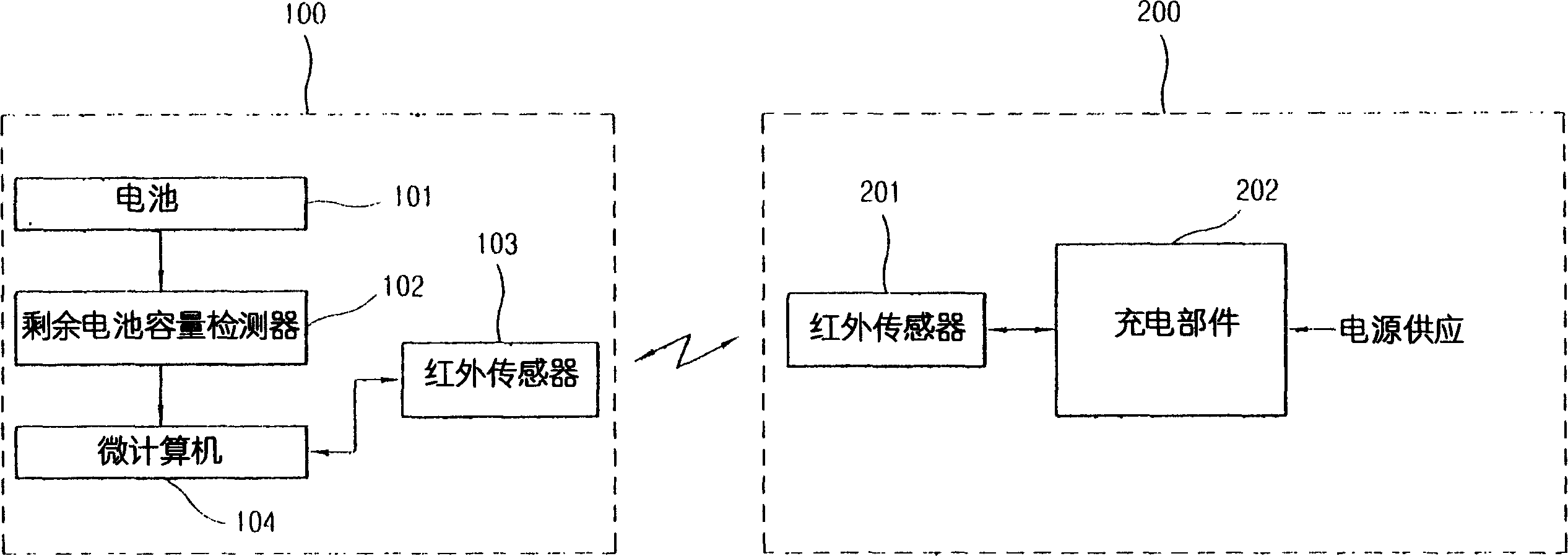
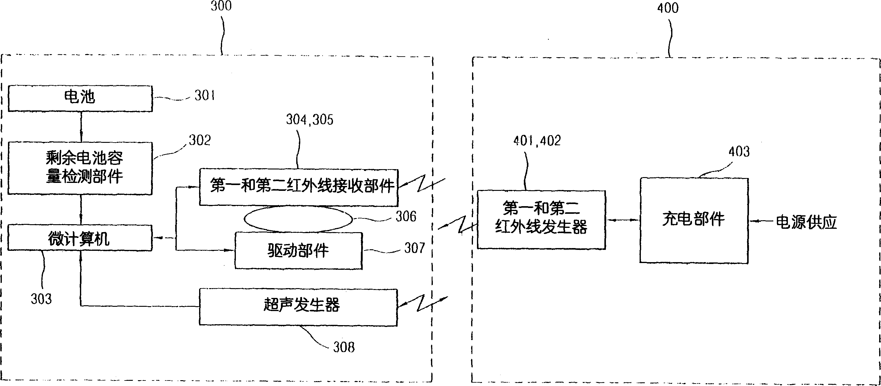
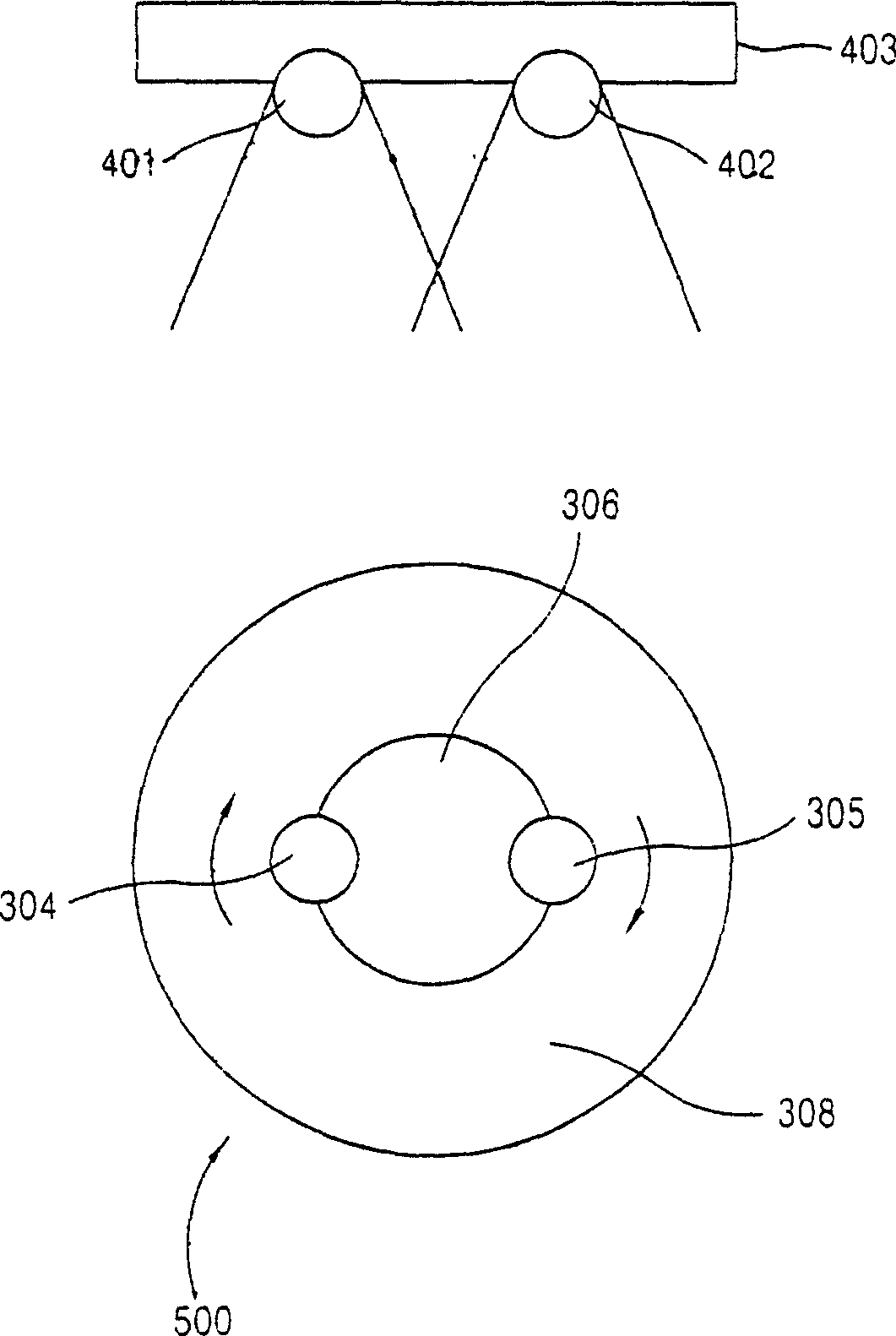
[0038]The automatic charging system and method of the cleaning robot of the present invention are characterized in that several infrared sensors are installed on the cleaning robot and rotate to accurately and quickly detect the infrared signal from the fixedly installed charging part, so the cleaning robot can accurately and quickly The power supply terminal of the cleaning robot can be accurately and quickly connected to the charging terminal of the charging part, and the cost of realizing the cleaning robot can be reduced.

[0039] will now refer to Figures 2 to 4 , illustrating a preferred embodiment of the present invention.

[0040] The automatic charging system and method of the cleaning robot of the present invention can be installed on a toy or any device that uses batteries to move.

[0041] figure 2...


PUM


Abstract

An automatic charging system of a robot cleaner includes: a rotating plate (306) installed at a robot cleaner; an infrared ray receiving unit (304,305) mounted at the rotating plate (306) and receiving an infrared signal generated from a power supply unit (400) while being rotated; a microcomputer (303) for moving the robot cleaner to the power supply unit (400) on the basis of the received infrared signal; and an ultrasonic generator (308) for generating a stop signal when the robot cleaner nears to the power supply unit (400). A robot cleaner can be accurately and quickly moved to a power supply unit for a rapid charging operation, and a cost for implementing the robot cleaner can be reduced.

Description

technical field [0001] The present invention relates to a cleaning robot, in particular to an automatic charging system and method for a cleaning robot. Background technique [0002] figure 1 It is a schematic block diagram showing the structure of the charging system of the cleaning robot according to the prior art. [0003] Such as figure 1 As shown, the charging system of the cleaning robot (not shown) includes a cleaning robot power receiving unit 100 and a cleaning robot power supply unit 200 for charging the battery 101 . [0004] The power supply unit 200 includes an infrared sensor 201 for communicating with the cleaning robot, and a charging part 202 for charging the battery 101 of the cleaning robot. The infrared sensor 201 is installed at the charging part 202, and generates an infrared signal in a predetermined direction. [0005] The power receiving unit 100 of the cleaning robot includes: a battery 101; a remaining battery capacity detector 102 for detectin...

Claims


Application Information

Patent Timeline
Patent Type & Authority Applications(China)
IPC IPC(8): A47L9/00A47L9/28G05D1/02
CPCG05D1/0225A47L9/009G05D2201/0203A47L9/2852A47L9/2873A47L9/2894G05D1/0242A47L2201/022A47L9/2805A47L9/2878G05D1/0255A47L9/28
Inventor 田炯臣禹春圭
Owner LG ELECTRONICS INC
Why Eureka
Try Eureka