Special device for thermal infrared imager test of laminate

A technology of infrared thermal imaging and special devices, which is applied in measuring devices, optical radiation measurement, radiation pyrometry, etc., to achieve the effects of avoiding cumbersome operation processes, improving detection efficiency, and reducing labor intensity

Active Publication Date: 2013-07-24
EGING PHOTOVOLTAIC TECHNOLOGY CO LTD
View PDF4 Cites 0 Cited by
  • Summary
  • Abstract
  • Description
  • Claims
  • Application Information

AI Technical Summary

Problems solved by technology

[0003] In order to overcome the shortcomings of the existing special device for infrared thermal image testing of laminated parts, the present invention provides a new type of special device for infrared thermal image test of laminated parts

Method used


Image

  • Special device for thermal infrared imager test of laminate
  • Special device for thermal infrared imager test of laminate
  • Special device for thermal infrared imager test of laminate

Examples


Embodiment Construction

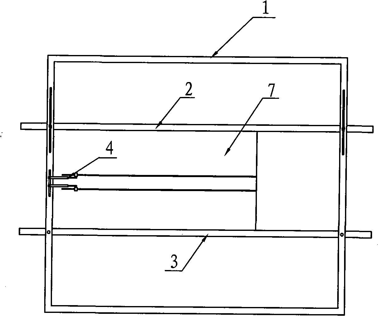
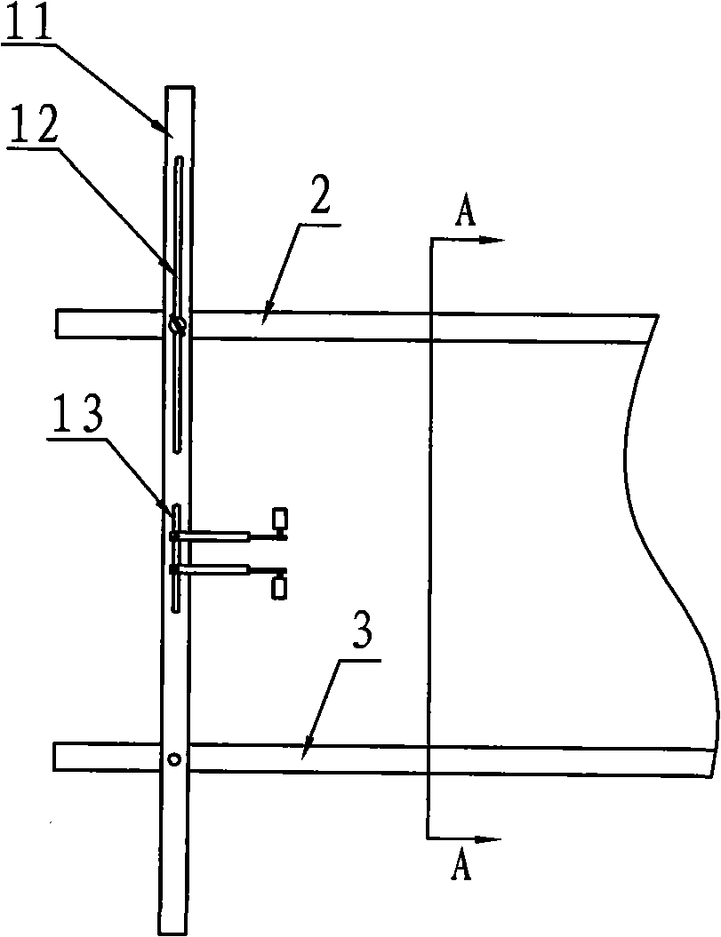
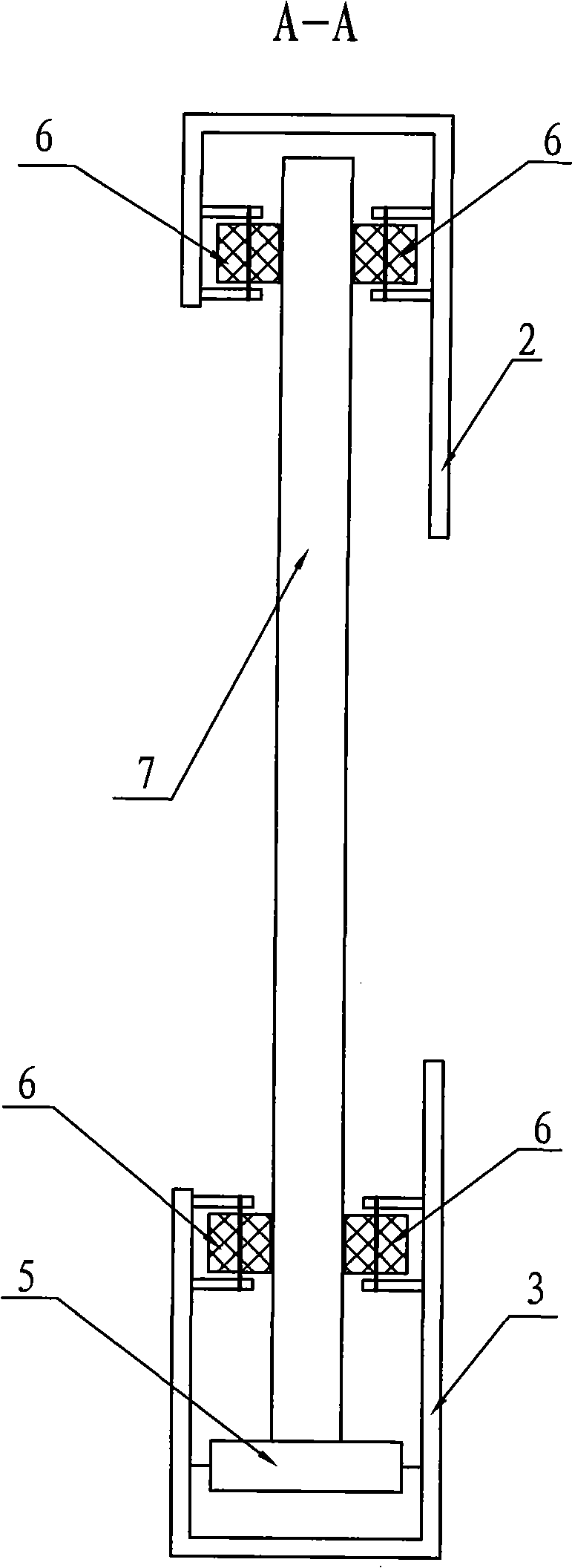
[0016] The special device for infrared thermal image testing of laminates according to the present invention, such as Figure 1~4 As shown, it includes a frame 1, an upper track 2, a lower track 3, a rolling contactor 4 and a bottom rolling rubber wheel 5. The frame 1 includes two vertical bars 11 arranged in parallel on the left and right, and the two vertical bars 11 The upper part of the upper section is provided with an upper rail adjustment groove 12, and an electrical connector adjustment groove 13 is arranged in the middle. In the upper rail adjustment groove 12 of the upper section of the straight rod 11, the cross-sectional shapes of the upper rail 2 and the lower rail 3 are both asymmetrical U-shaped, and the opening of the upper rail 2 is downward, the opening of the lower rail 3 is upward, and the bottom rolling rubber wheel 5 Set at the bottom of the lower track 3, the rolling contactor 4 is composed of a positive lead post 41 and a negative lead post 42, and a co...


PUM


Abstract

The invention relates to a special device for thermal infrared imager test of a laminate, comprising a framework, an upper track, a lower track, a rolling circuit closer and a bottom rolling rubber wheel. The framework comprises two vertical rods, the upper sections of the two vertical rods are provided with upper track regulating tanks, and the middles of the two vertical rods are provided with circuit closer regulating tanks. The upper track and the lower track are fixedly installed on the two vertical rods with equal height. A battery laminate is inserted into notches of the upper track and the lower track, and the rolling circuit closer is in contact with the anode and the cathode of the battery laminate. Since an insertion sliding structure is adopted among the battery laminate, the upper track and the lower track, and the distance between the upper track and the lower track can be regulated, the testing requirement of battery laminates with different specifications can be met. The sliding type power connection testing device greatly simplifies the operation of the operating personnel in a darkroom, reduces the labor intensity, improves the detecting efficiency without damaging the battery laminate, avoids the tedious operation process for respectively clamping the anode and the cathode, and thoroughly puts an end to false connection of the anode and the cathode.

Description

Technical field: [0001] The invention relates to a device for testing a photovoltaic module, in particular to a special device for testing an infrared thermal image of a laminate. Background technique: [0002] The main production process of photovoltaic modules is to laminate raw materials such as glass, solar cells, plastic packaging materials and back sheets, and vacuumize and heat them through a laminator. The semi-finished product before the frame is called a laminate. Fractures or hidden fractures of the cells in the laminate will cause the battery to open. This failure will affect the life of the module, so it is necessary to inspect the laminate before framing. In the dark room, the laminate is fed with current, and the cooled CCD image sensor is used to capture the light emitted by the current-passed battery to generate an image. Observing the situation of the battery from the image is a method that is currently used more. The current method of passing current thr...

Claims


Application Information

Patent Timeline
Patent Type & Authority Patents(China)
IPC IPC(8): G01J5/02
Inventor 杨振嵘陈鑫
Owner EGING PHOTOVOLTAIC TECHNOLOGY CO LTD
Why Eureka
Try Eureka