
Oil pan with variable oil mass

A technology of oil pan and oil quantity, which is applied in the direction of oil pan, engine components, machines/engines, etc. It can solve the problem of oil connection and separation between inner and outer oil pans, slow oil temperature rise in the inner oil pan, and zero There are many parts, etc., to achieve the effect of simple structure, fast oil discharge speed and reduced energy loss

Inactive Publication Date: 2019-01-04
DONGFENG MOTOR CORP HUBEI
View PDF11 Cites 9 Cited by
  • Summary
  • Abstract
  • Description
  • Claims
  • Application Information

AI Technical Summary

Problems solved by technology

Therefore, when the CN 101415914A engine is shut down, the connection of the oil and the separation of the oil after the engine is started are still realized through the opening and closing of multiple valves, which need to be connected or isolated from the inside and outside through the opening and closing of the temperature-driven communication valve and the oil return control valve. Complex, with many parts, it is difficult to accurately and quickly complete the connection and separation of oil in the inner and outer oil pans during engine operation
[0007] In CN 103573327A, there is a communication path between the inner and outer oil pans, so they are connected at any time, which is conducive to synchronous oil filling and oil discharge. However, due to part of the heat transfer to the outer oil pan during warm-up operation, the inner oil pan will be damaged. Internal oil heating rate slows down

Method used


Image

  • Oil pan with variable oil mass
  • Oil pan with variable oil mass
  • Oil pan with variable oil mass

Examples


Embodiment Construction

[0034] The following specific examples illustrate the present invention in further detail.

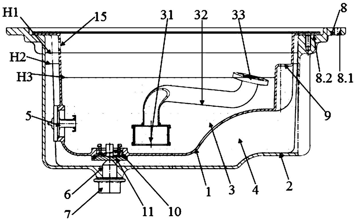
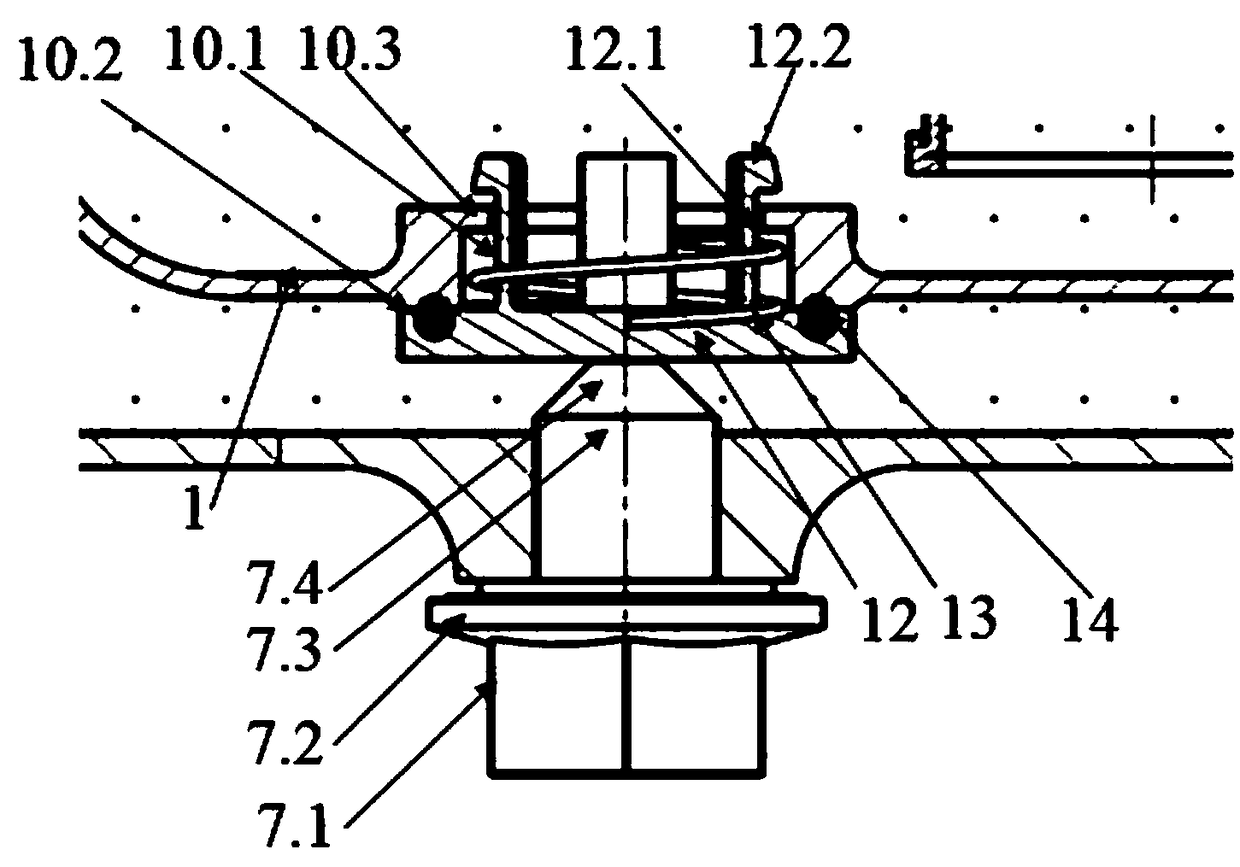
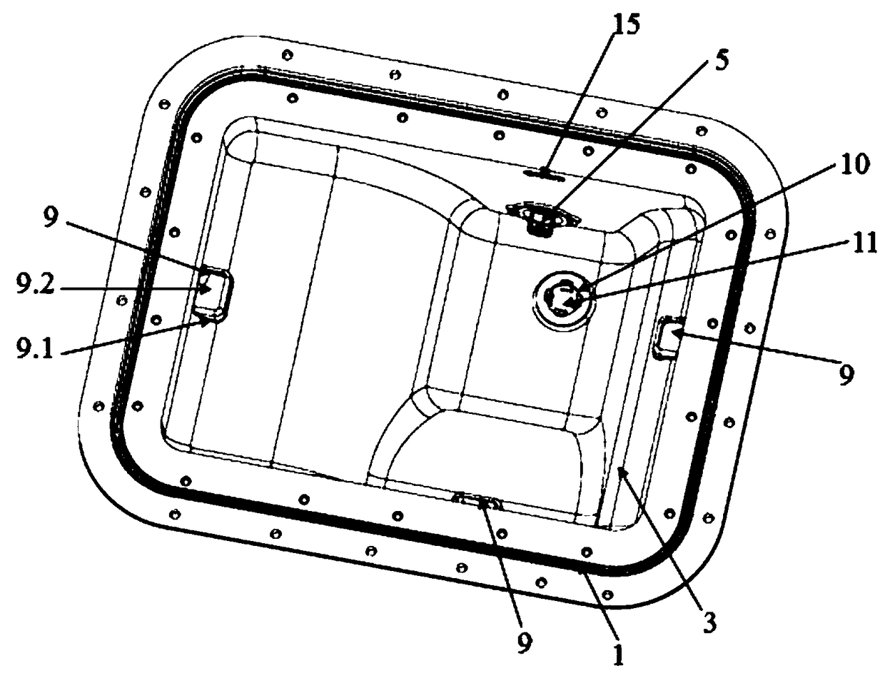
[0035] Such as figure 1 As shown, a variable oil volume oil pan provided by the present invention includes an inner oil pan 1 and an outer oil pan 2, the inner oil pan 1 has a first chamber 3, the inner oil pan 1 and the outer oil pan The second chamber 4 is formed between the two oil pans, the first chamber 3 is provided with a thermostat valve 5 communicating with the second chamber 4, the bottom of the outer oil pan 2 is provided with an external oil discharge port 6, and the external oil discharge The port 6 is provided with an external oil drain plug 7, and the opening of the outer oil pan 2 is provided with a mounting part 8 which is in sealing connection with the opening of the inner oil pan 1, and the second chamber 4 is the outer oil pan 2 and the inner oil tank. The circumferential gap and the bottom gap of the bottom shell 1 are connected, and the side wall of the first chamb...


PUM


Abstract

The invention discloses an oil pan with variable oil mass, wherein an opening of an outer oil pan is provided with an installing part which is in sealing connection with an opening of an inner oil pan; a plurality of overflow ports with the same height and communicating with a second chamber are arranged on the side wall of a first chamber circumferentially and at intervals; the overflow ports arelocated above a thermostat valve and the height is less than the maximum oil injection height of the second chamber; the bottom of the inner oil pan is provided with an inner oil discharge outlet atthe corresponding part of an outer oil discharge outlet; and an inner oil discharge plug capable of opening or closing the inner oil discharge outlet synchronously through linking with an outer oil discharge plug is arranged at the inner oil discharge outlet. In the invention, when the outer oil discharge plug acts, the inner oil discharge plug links to open or close the inner oil discharge outletsynchronously; the oil injection and oil discharge of the inner and outer oil pans are carried out simultaneously; the oil injection and oil discharge speed is quick, so the indirect responses of various valves are not needed; and then communication of the inner and outer oil pans can be finished accurately and quickly during the oil injection and oil discharge.

Description

technical field [0001] The invention relates to the technical field of automobile engines, in particular to a variable oil volume oil pan. Background technique [0002] When the car is cold-started at low temperature, the engine economy is poor. After driving for a period of time, the fuel consumption will improve after the temperature of the standby engine oil rises to about 60°C. This is mainly because the low temperature affects the viscosity of the engine oil, making the movement between The frictional resistance between them increases, resulting in energy loss. [0003] The prior art such as publication numbers CN 101415914A and CN 103573327A both adopt a dual-structure oil pan formed by setting an internal oil pan inside the external oil pan. Then return to the inner oil pan to achieve the effect similar to rapid warm-up; when the oil temperature rises to a certain value, the connecting valve (usually a thermostat valve) between the inner and outer oil pans is connect...

Claims


Application Information

Patent Timeline
Patent Type & Authority Applications(China)
IPC IPC(8): F01M11/00F01M11/04
CPCF01M11/0004F01M11/0408F01M11/0458F01M2011/0037F01M2011/0045F01M2011/0416F01M2011/0483
Inventor 黄洪浪王静秋唐元媛徐天添李建龙
Owner DONGFENG MOTOR CORP HUBEI
Learn More