Power supply managing topological structure

A topology, DC power technology, applied in emergency power arrangement, current collectors, electric vehicles, etc., can solve the problems of reducing the overall efficiency of the power system and increasing the cost.

Inactive Publication Date: 2004-09-22
O2 MICRO INT LTD
View PDF1 Cites 16 Cited by
  • Summary
  • Abstract
  • Description
  • Claims
  • Application Information

AI Technical Summary

Problems solved by technology

The second power conversion step adds further cost and reduces the overall efficiency of the power system

Method used


Image

  • Power supply managing topological structure
  • Power supply managing topological structure
  • Power supply managing topological structure

Examples


Embodiment Construction

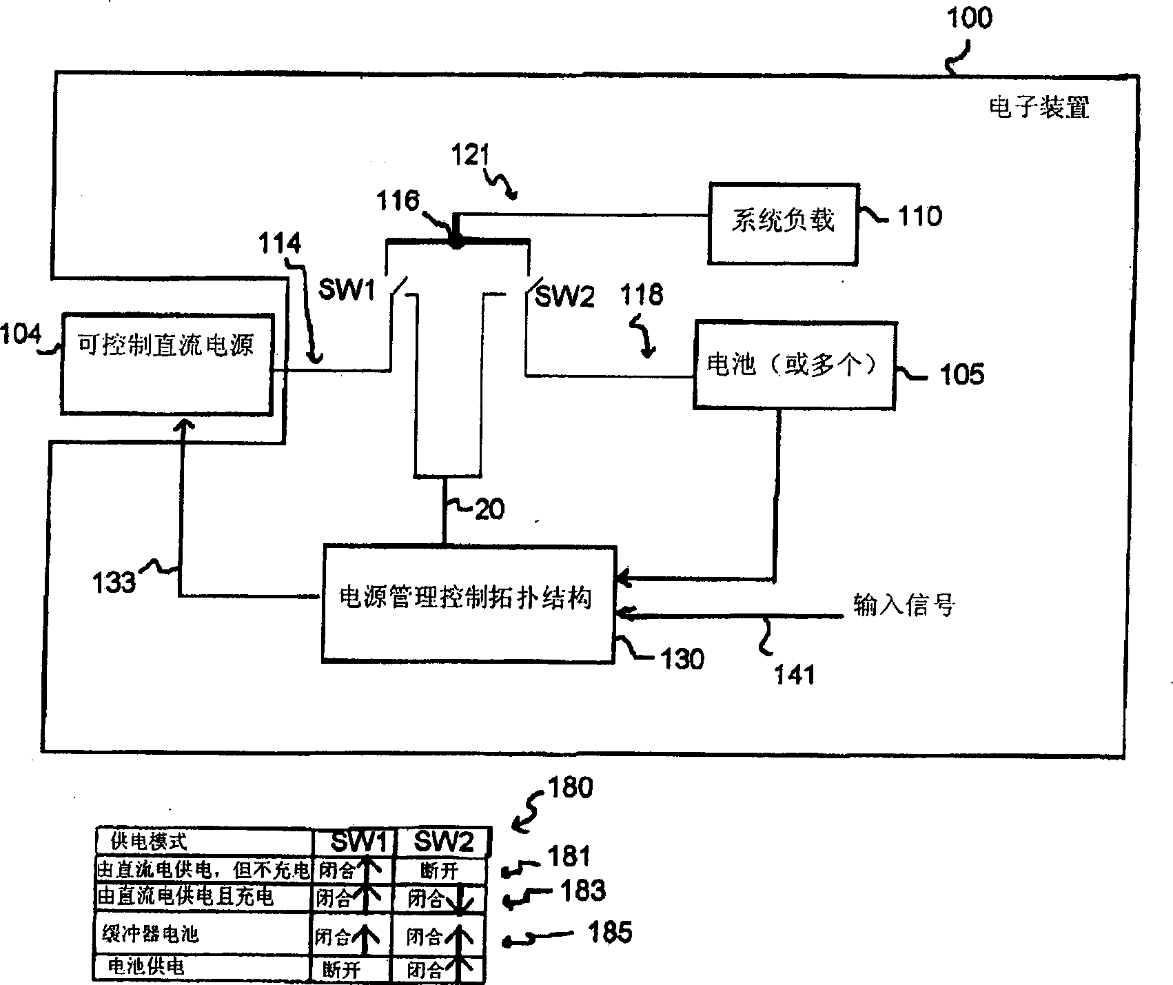
[0030]figure 1 Shown is a schematic block diagram of an electronic device 100 comprising: a system load 110 powered by a controllable DC power source 104 or a battery 105 , or a parallel connection of the controllable DC power source 104 and the battery 105 . Table 180 shows the positions of switches SW1 and SW2 for various power modes. In one embodiment, the controllable DC power source 104 may be a controllable adapter as further detailed herein, such as an ACDC adapter, which can power the system load 110 and the battery 105 with only one step of power conversion. In this way, an extra power conversion step typically used in other power systems (eg, a DC / DC converter providing a precisely controlled output to charge a battery) is avoided in this embodiment.

[0031] The electronic device 100 may be various devices known in the art, such as a notebook computer, a mobile phone, a personal data assistant, a power tool, an electric drive vehicle, and the like. The controllable...


PUM


Abstract

A power supply topology having a first path configured to be coupled to a controllable DC power source, a second path configured to be coupled to a battery, and a third path configured to be coupled to a system load, wherein the first, second, and third paths are coupled to a common node. A first switch is coupled to the first path to allow selective coupling of the controllable DC power source to the system load via the common node, and a second switch is coupled to the second path to allow selective coupling of the battery to the common node. The power supply topology may be used with existing adapters or with a controllable adapter to provide for a one step power conversion. The power topology may be utilized to enable the controllable DC power source and a battery to provide power in parallel to a system load.

Description

technical field [0001] The present invention relates to power management systems, and more particularly to various power management topologies for electronic devices. Background technique [0002] Various portable electronic devices have a power management system that monitors, controls, and directs the various power sources to power the system load of the electronic device. These power supplies typically consist of a fixed-output AC-DC (ACDC) adapter and one or more rechargeable batteries. The power system includes a power conversion module, such as a DC / DC converter, which converts the fixed DC voltage provided by the ACDC adapter into a precise and controllable variable output DC voltage to charge the battery. [0003] The power system supplies power to the system from the ACDC adapter or the main battery, if suitable conditions are met, and performs battery charging. As such, there is usually an ACDC power switch for selectively connecting the ACDC adapter to the syste...

Claims


Application Information

Patent Timeline
Patent Type & Authority Applications(China)
IPC IPC(8): H02J1/00H02J7/00H02J7/02H02J7/34H02J9/06
CPCH02J2007/0059H02J2007/0067H02J7/02H02J7/0027Y02T10/7055H02M2001/0045H02J7/34H02J7/0068H02J9/061H02J7/0057H02J7/0018H02J2207/20H02J7/0069H02J7/0025Y02T10/70H02M1/0045H02J5/00
Inventor 康斯坦丁·布克法拉·坡贝斯库·斯塔内斯缇玛利安·尼古拉戴诺·尼斯
Owner O2 MICRO INT LTD
Why Eureka
Try Eureka