Correcting method for electronic part mounting device and device for using said method

A calibration method and component technology, applied to measuring devices, electrical components, projection devices, etc., can solve problems such as time-consuming and complicated calibration operations

Inactive Publication Date: 2004-09-29
JUKI CORP
View PDF1 Cites 10 Cited by
  • Summary
  • Abstract
  • Description
  • Claims
  • Application Information

AI Technical Summary

Problems solved by technology

In addition, the calibration tasks such as the transfer and measurement of the jig substrate are complicated and time-consuming

Method used


Image

  • Correcting method for electronic part mounting device and device for using said method
  • Correcting method for electronic part mounting device and device for using said method
  • Correcting method for electronic part mounting device and device for using said method

Examples


Embodiment Construction

[0026] Hereinafter, a method for correcting a position recognition camera, an apparatus thereof, and an electronic component mounting apparatus using a jig substrate and a jig component for correcting the position of a recognition camera according to an embodiment of the present invention will be described with reference to the accompanying drawings.

[0027] This electronic component mounting apparatus 1 is a so-called multifunctional component mounting machine, and is configured to mount various electronic components such as surface mount components such as chip capacitors and chip resistors, and multi-lead components such as QFPIC.

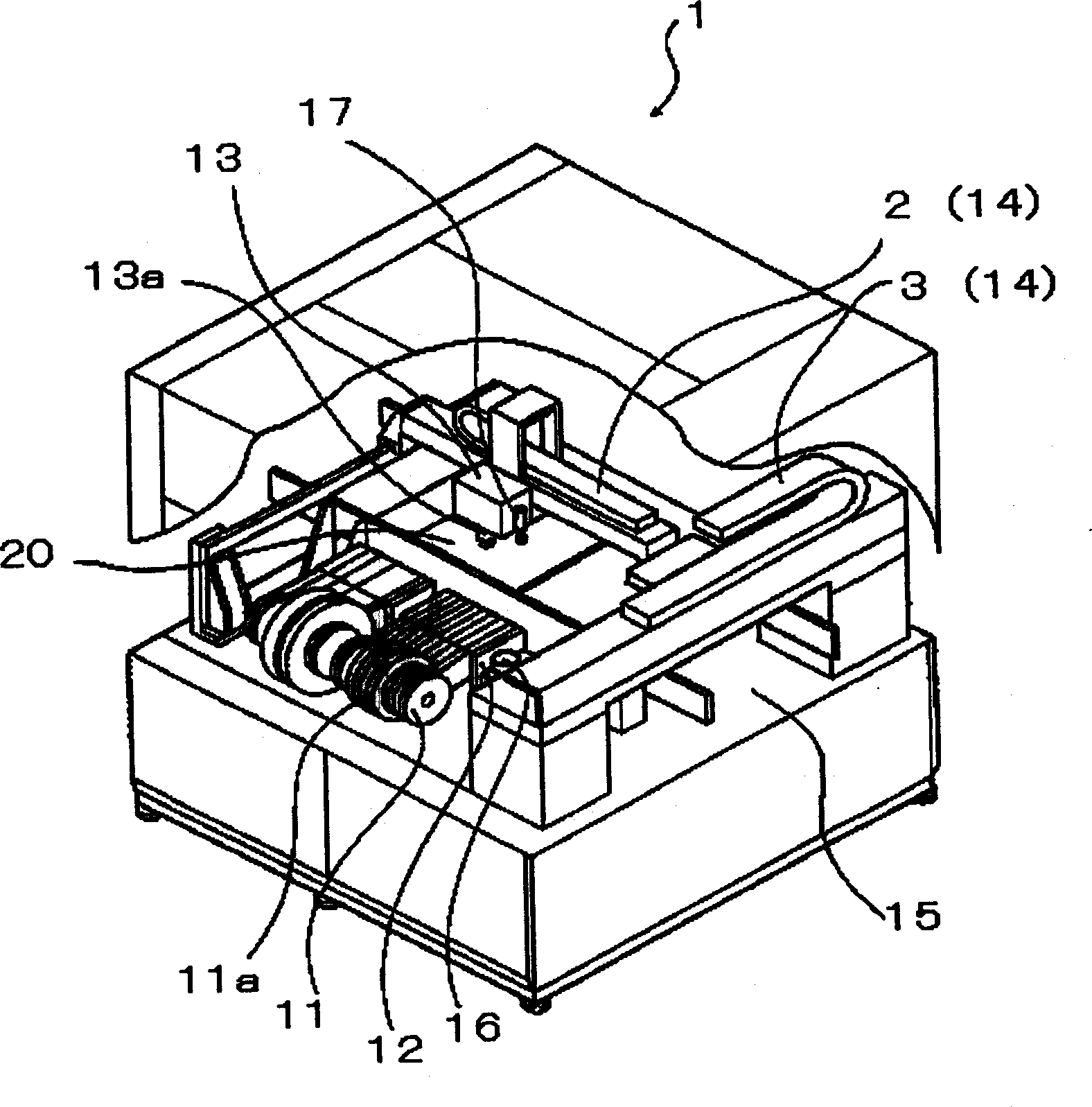
[0028] figure 1 It is a schematic diagram of the electronic component mounting apparatus. As shown in this figure, the electronic component mounting apparatus 1 has: a component supply unit 12, and a substrate conveyance path 15 extending from the central part in the left and right directions slightly behind, and is arranged on the electronic co...


PUM


Abstract

To provide a method for calibrating the position of a camera by which a deviation between the mutual coordinate system of the part recognition camera and coordinate system of the substrate recognition camera can be calibrated simply and rapidly.In the method for calibrating the deviation of the places of the cameras, a fixture part 30 enabled by both recognition methods is used. The method has an image pick-up process in which the part 30 is image-picked up by the part recognition camera first, the image pick-up process in which a fixture substrate is image-picked up by the substrate recognition camera 17, a mounting process in which the fixture part 30 is mounted, a computing process in which the center of the part is obtained by the substrate recognition camera 17 and the quantities of displacements obtained respectively with the place of the recognition center of the camera 17 are computed in the mark of the fixture part 30 after the mounting, and a calibrating process in which the coordinate systems of the camera 17 or the camera 16 are calibrated on the basis of the quantities of the displacements. (C)2005,JPO&NCIPI.

Description

technical field [0001] The present invention relates to a camera position deviation correction method and device for correcting a mutual deviation between a coordinate system of a component recognition camera and a coordinate system of a board recognition camera in an electronic component mounting apparatus and the like, and camera position correction Fixture substrates and fixture components used. Background technique [0002] In an electronic component mounting apparatus, a board recognition camera is used to image a board mark or an IC mark on a board carried into a main body of the device to recognize the position of the board. Then, electronic components mounted on the substrate are imaged by a component recognition camera to perform position recognition, and based on the recognition results, the positions of the electronic components are corrected, and then the electronic components are mounted on the substrate. [0003] In this case, if the coordinate system of the p...

Claims


Application Information

Patent Timeline
Patent Type & Authority Applications(China)
IPC IPC(8): H05K13/04G01B21/00G03B15/00G03B29/00
Inventor 师冈博明石泽勇治
Owner JUKI CORP
Why Eureka
Try Eureka