System and method for measuring the thickness of a layer of coating

a technology of coating and thickness, applied in the field of radiometric measurement, can solve the problems of not having the same desired accuracy or simplicity, the inability to measure directly on the coating of the substrate, so as to achieve the effect of improving the relative accuracy of measurement, improving the accuracy and resolution of obtained values, and improving the accuracy of measuremen

Inactive Publication Date: 2012-02-09
TETRA LAVAL HLDG & FINANCE SA
View PDF3 Cites 5 Cited by
  • Summary
  • Abstract
  • Description
  • Claims
  • Application Information

AI Technical Summary

Benefits of technology

[0007]By using IR radiometric sensor technology for measuring at one wavelength, a large surface may be measured and an average value calculated. The value obtained has a higher accuracy than measurements on a more limited surface, using the advantages of “optical averaging”. Furthermore, the radiometric measurement method is very suitable for the...

Problems solved by technology

If the substrate receiving the coating has low reflection it may be difficult and in some cases even impossible to measure directly on the coating of the substrate.
Also for substrates having an uneven surface or havin...

Method used


Image

  • System and method for measuring the thickness of a layer of coating
  • System and method for measuring the thickness of a layer of coating
  • System and method for measuring the thickness of a layer of coating

Examples


Embodiment Construction

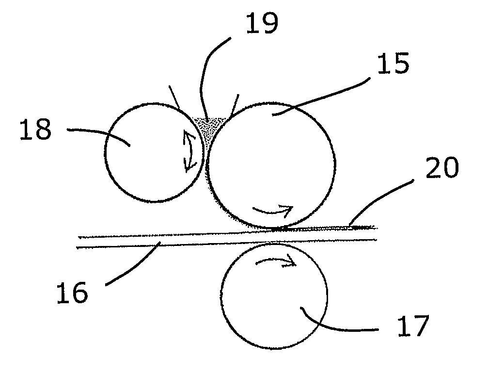
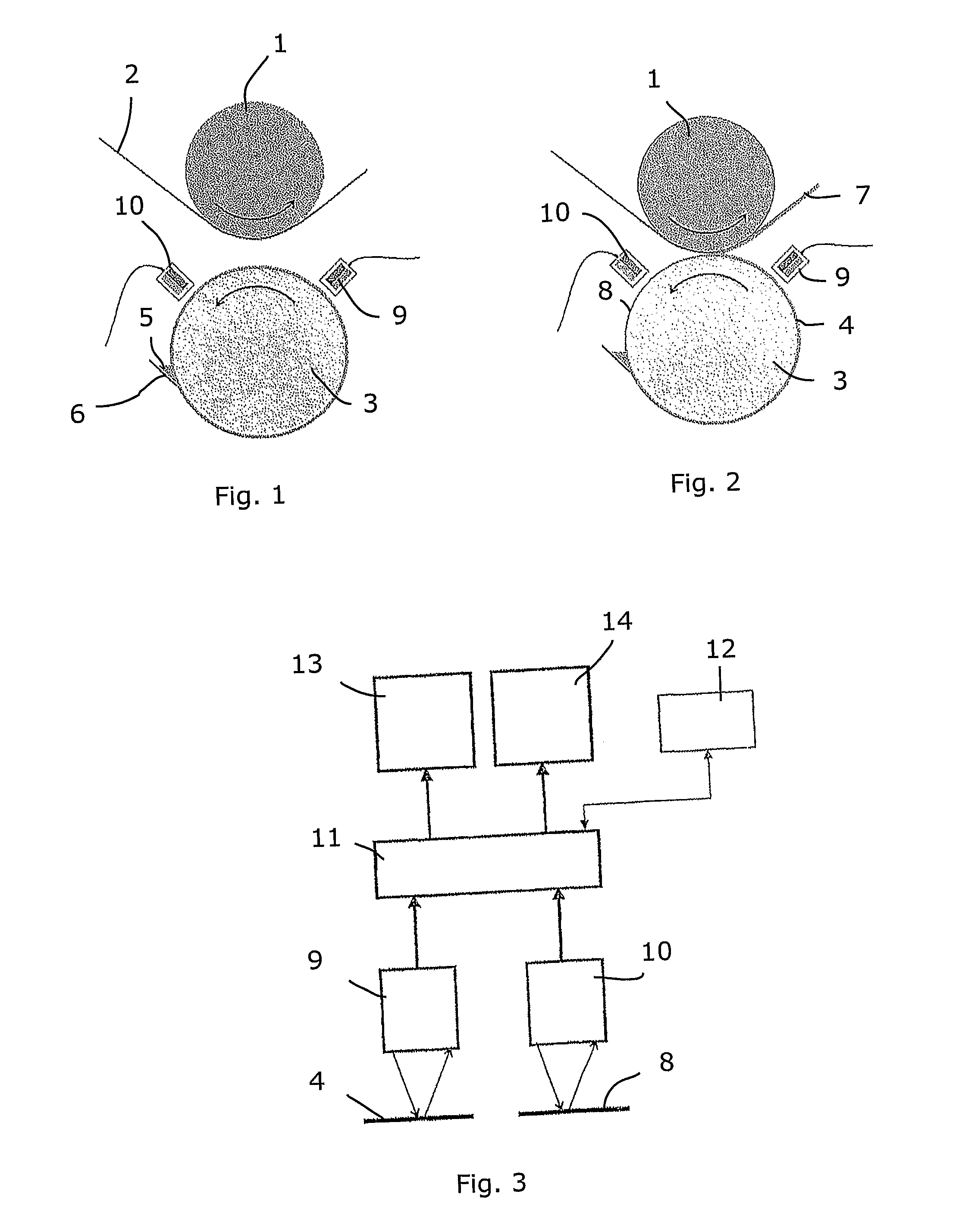
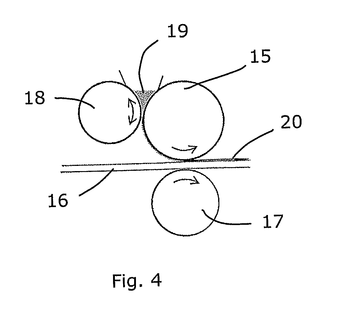
[0019]In the FIGS. a set-up for measuring according to the present invention is indicated. The shown embodiment is only one example and a person skilled in the art realises that the exact form of the different parts may vary. For example the coating may be applied at a straight part of the substrate and not at a roller.

[0020]In the shown example a substrate 2 is fed over a roller 1. A coating roller 3 is placed opposite the roller 1 of the substrate 2. The coating roller 3 may have different embodiments, one embodiment being a so-called anilox roller. A layer 4 of coating is deposited on the coating roller 3. The coating is given to the coating roller 3 by means of a pocket 5 and a stripper 6. The pocket 5 is in practice the area between the stripper 6 and the coating roller 3, which area is constantly supplied with coating. The stripper 6 spreads the coating onto the surface of the coating roller 3, giving the layer 4 of coating. By altering the position and / or inclination of the s...


PUM


Abstract

A system and a method for measuring the thickness of a layer of coating deposited on a substrate indirectly measures the thickness of the layer of coating on the substrate by measuring the thickness of layers of coating on a coating roller before and after the coating is transferred from the coating roller to the substrate. To measure the thickness of the layers of coating on the coating roller two sensors are used directed to respective layer on the coating roller. The sensors have IR radiators and IR detectors.

Description

TECHNICAL FIELD[0001]The present invention concerns a system for radiometric measuring of a coating on a substrate and a method for liquid film coating on a substrate comprising the step of measuring the coating thickness. The invention also concerns use of the system and the method.[0002]The system of the present invention may for instance use the measuring principle described in WO 02 / 42077.BACKGROUND OF THE INVENTION[0003]It is known that different fluids, such as coatings, absorb different, specific bands of IR (infrared) radiation. This knowledge is used in radiometric measuring where absorption of radiation wavelengths within the IR area is used. The main or other absorption bands of a fluid to be measured is used in that the change of energy when the radiation passes through the film is analysed. An important condition for such a measurement is that the substrate on which the fluid is received reflects a major part of the radiation in the selected wavelength range. Thus, by d...

Claims


Application Information

Patent Timeline
IPC IPC(8): G01J3/00
CPCG01B11/06B41F33/0063G01B11/0625
Inventor BENTMAR, MATSCRONVALL, LEIF
Owner TETRA LAVAL HLDG & FINANCE SA
Why Eureka
Try Eureka