Multichannel remote control device

A remote control device, multi-channel technology, applied in the communication, instrument, signal transmission system and other directions between multiple stations, can solve the problem of inconvenience for players

Inactive Publication Date: 2004-10-13
PERICOM TECH (SHANGHAI) CO LTD
View PDF0 Cites 8 Cited by
  • Summary
  • Abstract
  • Description
  • Claims
  • Application Information

AI Technical Summary

Problems solved by technology

Synchronous operation between transmitters can effectively avoid conflicts between channels, but the realization of synchronous op...

Method used


Image

  • Multichannel remote control device
  • Multichannel remote control device
  • Multichannel remote control device

Examples


Embodiment Construction

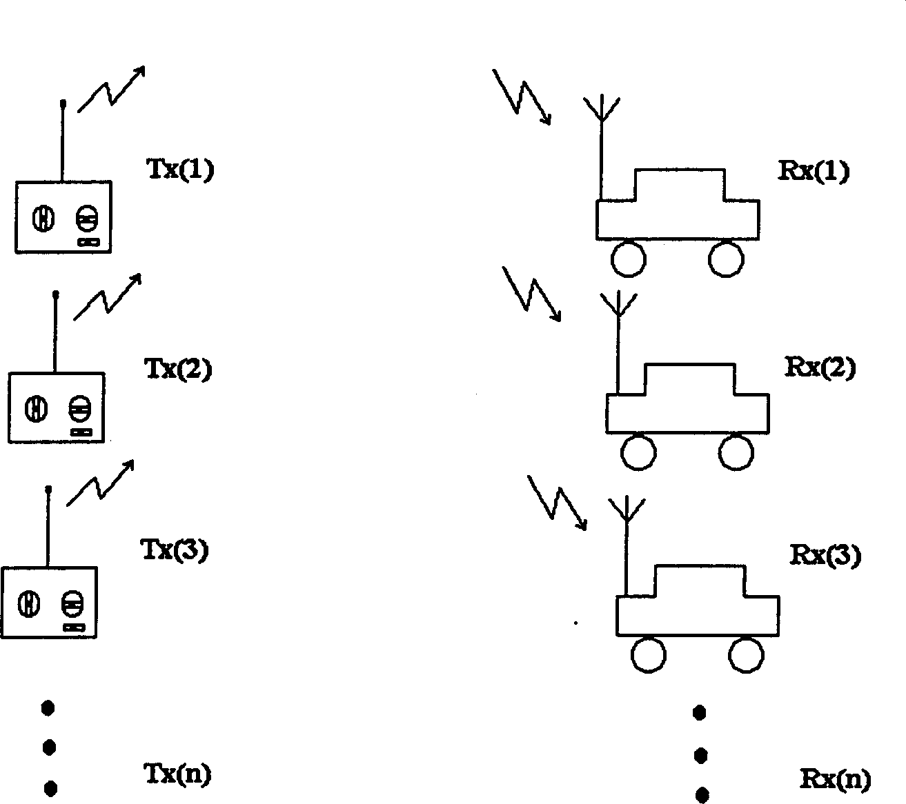
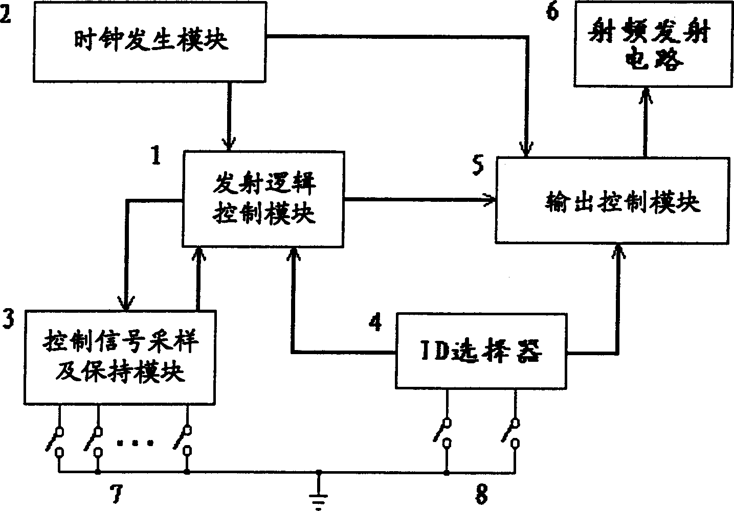
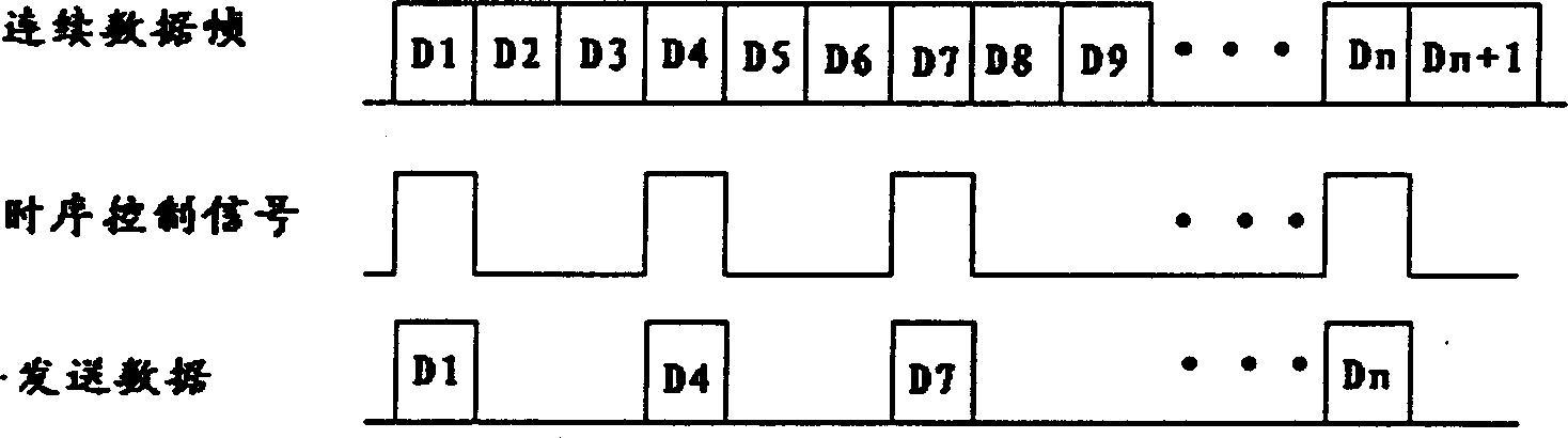
[0039] The purpose of the present invention is to provide a multi-channel remote control device, including a plurality of transmitters and a plurality of receivers, assign their own ID, the transmitter and the receiver through the ID to achieve one-to-one control, the transmitter uses the same frequency There is no synchronous operation between carriers, and the transmitter uses different transmission timings according to different IDs to avoid interference between channels, that is, each channel sends several frames of data in a shorter period within a certain period of time and selects the data to send time point, it can be guaranteed that each channel has at least one frame of data received without interference in each cycle, that is, the receiver can receive at least one frame of data from each transmitter in each cycle. frame complete data. In order to achieve the above goals, the transmitter encodes the control information that needs to be sent. Each data unit, that is, ...


PUM


Abstract

The invention provides a multichannel remote controller, including several transmitters and several receivers. The transmitter includes: instruction select switch, ID select switch, signal sampling control and holding module, ID selector, clock generator module, radio emitting circuit, and output control module, modulating continuous data frames into a signal with a certain timing sequence structure; transmit logic control module, and further including coding and data frame assembling parts. The receiver includes: receive logic control module, radio receiving circuit, ID select switch, ID selector, driving circuit, receive logic control module, and further including decoding part, checking part and ID comparing part. It uses a single carrier wave, transmits and receives in no need of many circuit structures, and designs that all the channels use different transmit timing sequences and ID, omitting synchronous operation and further simplifying the structure.

Description

technical field [0001] The invention relates to a multi-channel remote control device, in particular to a multi-channel remote control device which uses different sending timings for transmitters with different IDs. Background technique [0002] The current known multi-channel remote control toys mostly use the following two control methods: [0003] 1. Using different frequency carriers, [0004] In this method, multiple transmitters use different carrier frequencies to transmit data, and receivers are also set to receive data on corresponding frequencies. Transmitters transmit continuously without interfering with each other due to different carrier frequencies. The structure of the transmitter and the receiver is required to correspond one by one, and the versatility is poor. To have carriers of several frequencies at the same time, the structure of the transmitter and receiver becomes more complicated, and the cost is also increased. [0005] 2. Using the same carrie...

Claims


Application Information

Patent Timeline
IPC IPC(8): H04Q9/14G08C17/02G08C19/00H04B7/24
Inventor 徐平
Owner PERICOM TECH (SHANGHAI) CO LTD
Why Eureka
Try Eureka