Clamping chuck equipment

A chuck, equipment technology, applied in mechanical equipment, discharge tube, sleeve/socket connection, etc., can solve problems such as heat loss, wafer uniformity reduction, yield reduction, etc.

Inactive Publication Date: 2004-10-13
TEGAL CORP
View PDF1 Cites 2 Cited by
  • Summary
  • Abstract
  • Description
  • Claims
  • Application Information

AI Technical Summary

Problems solved by technology

Not only does convective heat loss reduce uniformity across the wafer during processing, but throughput is also reduced due to the extended time heaters take to heat the wafer prior to etching

Method used


Image

  • Clamping chuck equipment
  • Clamping chuck equipment
  • Clamping chuck equipment

Examples


Embodiment Construction

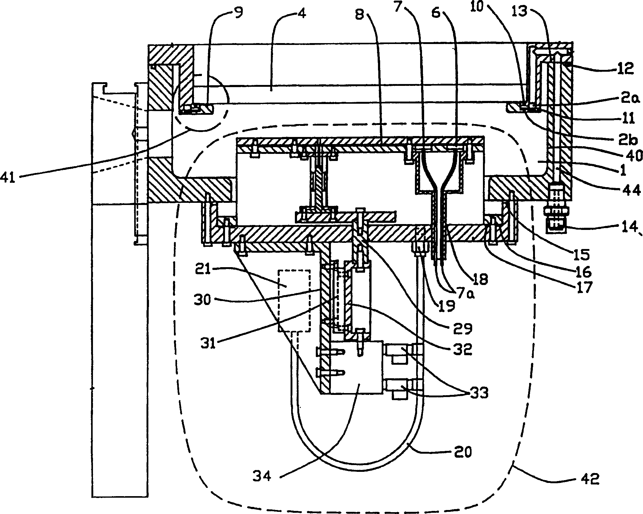
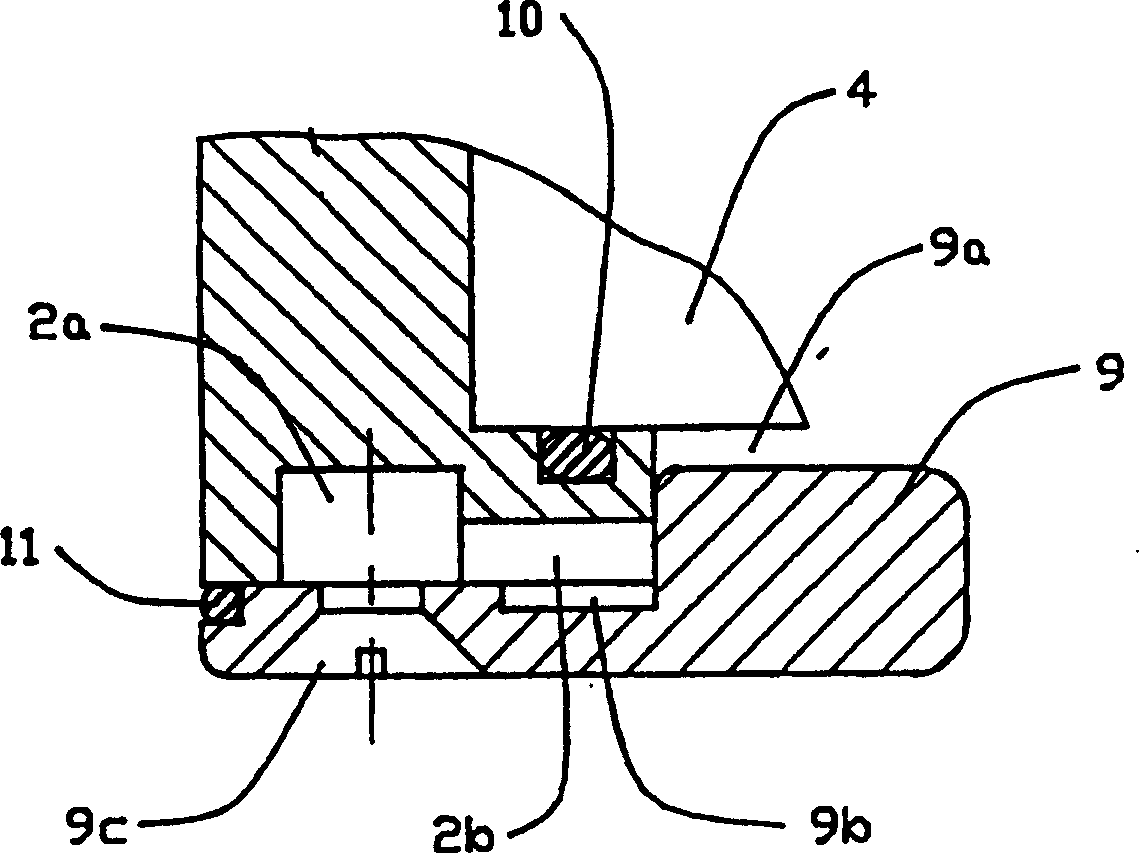
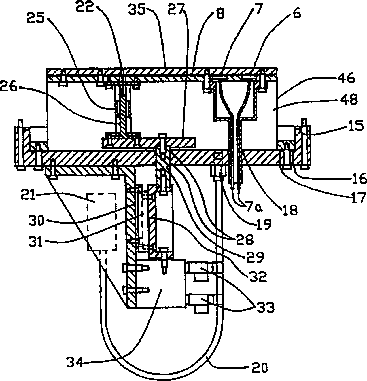
[0011] use figure 1 An embodiment of a monolithic device according to the invention is illustrated in a cross-sectional view of FIG. The apparatus comprises a reaction vessel 1 formed with a top quartz window 4, a cylindrical vessel side wall 40, and a wafer chuck forming and chassis assembly 42. Beneath the top quartz window 4 and along its perimeter is a gas delivery system 41 . A gas inlet 14 provides reactants into the vessel. After the reactant enters the gas inlet 14, it enters the annular gas cavity 2a through the U-shaped gas channel. The lumen is figure 2 Part of the gas delivery device shown. exist figure 2 In the process, the gas enters the annular gas booster 9b from the annular gas inner chamber 2a through many slots 2b. The gas inner cavity 2a and the gas booster 9b are mainly used to maintain a suitable pressure difference. The gas flows from the annular gas booster 9b into the vessel 1 through the continuous annular space 9a between the top quartz wind...


PUM


Abstract

This invention relates to a plasma reactor apparatus (1) having improved etch uniformity and throughput. Higher etch uniformity is achieved through the use of a new gas delivery mechanism (9a) and a thermally insulated wafer chuck (42). The vacuum insulated chuck (42) also results in lower energy consumption and higher throughput.

Description

[0001] This case is a divisional application of an invention patent application with an application date of March 28, 1996, an application number of 96194041.7, and an invention title of "Plasma Etching System". technical field [0002] The present invention relates to an improved plasma reactor, in particular to a reactor capable of improving etching uniformity and yield. Background technique [0003] Plasma etching has become an important process in the manufacture of semiconductor devices in integrated circuits. A key requirement of any plasma process for fabricating semiconductor devices is that the electrical characteristics of the fabricated devices must be uniform and consistent across the wafer. In other words, the plasma etch process must enable devices with high uniformity in thickness, size, and cross-section. However, as the diameter of the wafer increases and the size of the devices decreases, the difficulty in achieving such uniformity increases. Plasma etch ...

Claims


Application Information

Patent Timeline
Patent Type & Authority Applications(China)
IPC IPC(8): H01L21/302H01J37/32H01L21/3065
CPCH01J37/3244Y10T279/23H01J37/32449H01L21/20H01L21/30
Inventor 弗拉蒂米尔·E·莱博维克马丁·L·朱克
Owner TEGAL CORP
Why Eureka
Try Eureka